This thread has been locked.

If you have a related question, please click the "Ask a related question" button in the top right corner. The newly created question will be automatically linked to this question.

UCC28C45-Q1: PWM pulse skipping

Part Number: UCC28C45-Q1

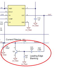
Hi, iam using UCC28C45-Q1 for flyback design, but my pwm pulses are skipping and also cs pin is picking noise even after using RC filter with lower cutoff frequency. Also is there any issue if we use ic ground and power ground as same.

  • RP,

    Can you post some waveforms and maybe a schematic detailing where/how you are making your measurements?

    Steve

  • green one is the out pin of ic wrt ic ground, blue one is Vds of Mosfet, black is the Cs pin wrt ic ground.

  • Here blue is Vgs(out), red is Cs pin, black is gate current 
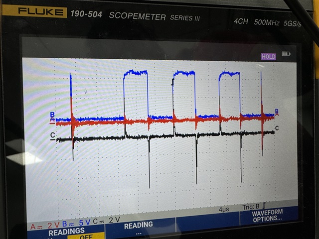
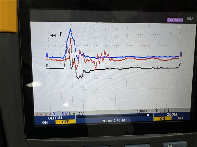
Here blue is Vgs(out), Black is gate current, red is cs pin

  • What are the line/load conditions resulting in the waveforms you've attached? Please label and describe as accurately as possible. Also, can you attach scope images instead of pictures of Fluke scopemeter?

    Steve

  • Hi Steven, as of now iam testing without any load. iam giving 20-30V as input also ic iam directly powering up with 12V supply. blue waveform is out pin of ic, black is gate current and red is cs pin. iam driving fet without level shifter. Ron 10ohm, Roff 5ohm in series with a diode.

    I want to get 12V output for 100-400V DC input.

  • Work to clean up your waveforms, use proper CS filtering, make sure your current and voltage loops are stable, be sure to apply slope compensation. Check your power stage calculations and loop compensation through TI Power Stage Designer. 

    regards,

    Steve 

  • for cs filtering, iam using 2.2k resistor and 220p cap. So, Fc will be around 329khz. but still iam getting noise. Also, slope compensation is must for ccm. but for dcm we can work without slope compensation. iam designing my circuit for dcm mode. for current and voltage loop iam using same R &C as suggested by ti power design.

  • Hi,

    You can estimate the CS threshold based on the COMP voltage so if CS noise reaches this threshold the pulse will be terminated. So you need make filter big enough to reduce the noise below the CS threshold. If you still see the noise exceeding the threshold when the filter looks not reasonable then you need to consider if any improvement can be made on your layout to help reduce the noise.

    You can also consider to add active leading edge blanking like the below red circled if you confirm the narrow pulses due to the noise.

    But critical step is to improve your layout which can help the most with minimum cost and board space.