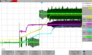
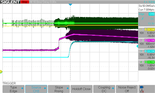
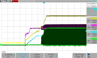
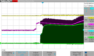
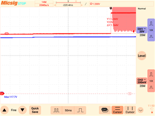
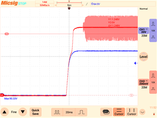
I have a forward converter with an input range of 120-190Vdc. I have the UVLO set at approximately 115V. If I turn on the supply slowly, it works fine, seen in the first picture PIC 1. However, if I do a rapid increase, it turns on around 90V, seen in the second picture PIC 2. There is no over-shoot on the input supply. CH1 BLUE is the input supply. CH2 RED is the UVLO pin.
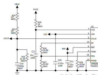
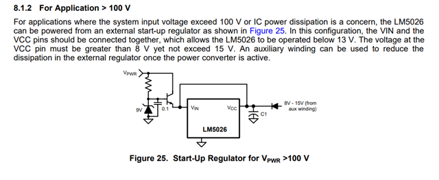
Per Figure 26, R1 is 2M and R2 is 21.5K, which should give 40V of hysteresis and a turn-on of about 115V.
What is going on here?
PIC1
PIC 2
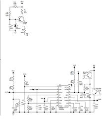
Circuit