Other Parts Discussed in Thread: BQ2970, BQ25895,
Hello,
I have the same requirements as described in this topic
To make it more convenient, I just copied the original topic here.
In my application, I have to use 2x 18650 batteries in parallel for capacity reasons. At the same time, for marketing reasons, I need to use removable 18650 elements, using a battery holder on board, and so the chance that batteries might be inserted backwards is definitely not negligible.
I was thinking of protecting each battery with a BQ2970, adding an extra mosfet to keep the charge mosfet off, as mentioned in a few posts, and then connect the output of the two protection circuits in parallel.
Would this work? or would you recommend a better/alternative solution?
FYI the charger is implemented using a BQ25895 on the main board - and hence can never be connected wrongly.
Looking forward to reading from you.
The answer
You need to add a small signal NFET whose gate is is connected to ground, the source and drain across the gate, and source of the charge FET to short them together in the event of a reverse charger connection. In the event of a reverse current, the FET will turn off and protect the batteries. We have a schematic of this configuration for a similar device for reference. See Q2 in Figure 21 on this document: http://www.ti.com/lit/ug/sluubp4/sluubp4.pdf
As Shawn Hinkle recommended in the original thread I choose BQ2980 for protection. However, it seems that the suggested protection protects the battery against the reverse polarity of the charger. But in my case (I think in the original topic also) I need to protect my device against the reverse polarity of a battery (as mentioned before, I use holders for 18650 batteries, and inserting the battery the wrong way is very easy). Also, It's possible to connect one battery the correct way, and another wrong.
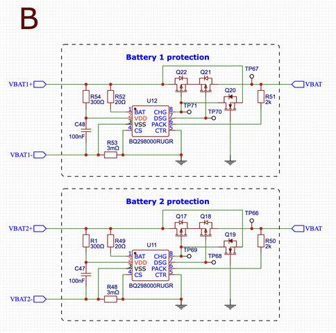
According to your answer, an NFET should be placed between gate and source of the charge FET, I drew a schematic:
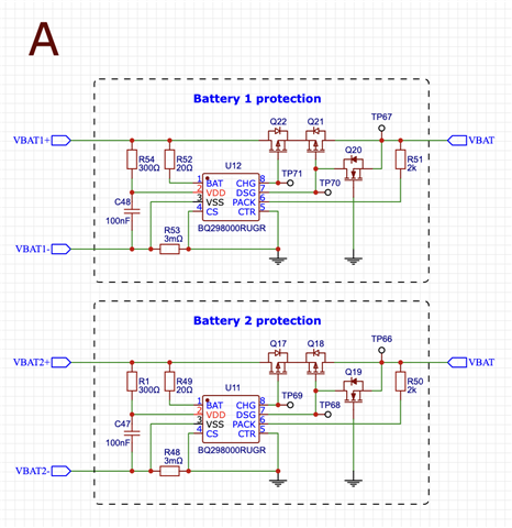
But maybe the NFET should be placed for discharge FET?
I'm looking forward to your answer. I appreciate any help you can provide.