This thread has been locked.

If you have a related question, please click the "Ask a related question" button in the top right corner. The newly created question will be automatically linked to this question.

HD3SS3220: Could you please help me check if the schematic is correct

Part Number: HD3SS3220

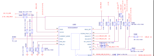
As shown in the figure below, we have designed HD3SS3220IRNHR to reserve both GPIO mode and I2C mode. Please help check if the circuit is correct in both modes, as our host's GPIO voltage threshold is 1.8V, and we have reserved 1.8V for both USB ID and int pull-up

  • Hi Tony,

    1. You may want to add 4.7K pullups for the SCL and SDA pins if you plan to use I2C mode. These would also work with the open-drain outputs OUT1/OUT2 when using GPIO mode. 

    2. Are you using the USB VBUS to power VDD5 on the HD3SS3220? This is only valid when operating as a UFP.

    3. I recommend adding one 0.1uF and one 1uF de-coupling capacitors near the VDD5 and VCC33 pins. 

    Best,

    Shane

  • We also have a question about whether the HD3SS3220IRNHR 5PIN VBUS-DET chip can work when it detects a lack of power.

    Because when we insert a USB flash drive into TYPEC, we need the I2C chip to inform the module to connect the USB flash drive to it, and then the other 5V power on the PCB board of the empty box will be supplied to USB-VBUS, allowing us to use the USB flash drive

  • Hi Tony,

    We also have a question about whether the HD3SS3220IRNHR 5PIN VBUS-DET chip can work when it detects a lack of power.

    VBUS_DET will detect the presence or lack of power on the VBUS.

    It sounds like you want to control your VBUS enable, which can be done using the ID pin. The ID pin will remain high until it sees a device attached. If the attached device is a UFP, the 3220 expects to provide power as the DFP and ID will go low. I made a diagram to help show how this typically works:

    If you want to use I2C to detect attachment, you can read from the ATTACHED_STATE register on the HD3SS3220

    Best,

    Shane