This thread has been locked.

If you have a related question, please click the "Ask a related question" button in the top right corner. The newly created question will be automatically linked to this question.

LM63635C-Q1: LM63635C-Q1 Rboot Calculation

Part Number: LM63635C-Q1

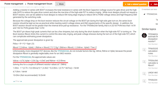
Search the E2E, found some similar calculation article for Rboot calculation. Just want to check for LM63635C-Q1, also could use same calculation formula.

Checked spec, not found related parameter that have been marked with red as following picture. 

Could you support to provide these values?

  • Hello,

    This device was not designed for resistance in series with the BOOT capacitor and TI does not recommend the use of such a series resistance.  There are critical control circuits that "float" on the SW node, and use the BOOT supply for their energy source.  Any impedance introduced in this source may disrupt the function of these circuits. Large resistances can interfere with the proper operation of the gate drive circuits, as well as certain control circuits that use the BOOT capacitor for energy supply.  This resistance can reduce the charging energy available to the BOOT capacitor and limit the transient current that can be supplied by the BOOT capacitor to the power FET gates and other control circuits.  Regulator misbehavior may include, but is not limited to, erratic switching at low input voltages and/or cold temperatures as well as possible regulator damage.  A resistance should only be used if and when it is determined that such resistance is the only way to mitigate any EMI issues that may be encountered.  In some cases, a Schottky diode can be used between the VCC supply of the regulator and the BOOT pin, to help recharge the BOOT capacitor more fully.  In any case, the customer would be responsible for testing all aspects of the design to ensure proper operation with such a resistor in place.  If the customer insists on using a series BOOT resistor, the application must be fully tested over the entire electrical and environmental conditions appropriate to the customer's application.  At a minimum, start-up, drop-out, and load transient testing should be performed at the lowest expected temperatures and the lowest expected input voltages. 

    Best regards,

    Ridge

  • Hi, Lahti,

    Thanks your reply.

    Agree with your suggestion. As I know, the Rboot resistor has a certain influence on the HS switching on& off  time and also will decrease the efficiency and bring some thermal issue. Of course, if we added Rboot resistor in our design, we will do some worst case test- low temp.(-40 degree) & low input voltage ( 4.0V)...even including some environment tests..

    But currrently just do some study about the Rboot calculation, do you have some idea or comments?

    And for Rboot selection, do you have some advice for the value range from your experience.

    Eg: Supposing we choose a Rboot - 20ohm, how to judge how big influence on the High-Side driver? or quickly evaluation formula..

  • Hello,

    TI does not recommend using a BOOT series resistance for this device. Please refer to the above post.

    Best regards,

    Ridge

  • OK, thanks your feedback!