This thread has been locked.

If you have a related question, please click the "Ask a related question" button in the top right corner. The newly created question will be automatically linked to this question.

LM5148-Q1: Clickling sound from switch mode circuit

Part Number: LM5148-Q1
Other Parts Discussed in Thread: LM5148

Hi,

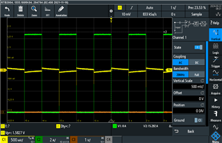
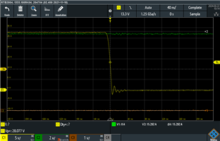
When I am loading my supply, I can hear this clicking sound from the circuit.

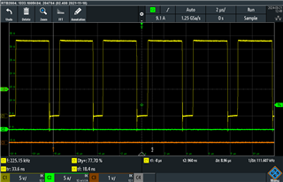
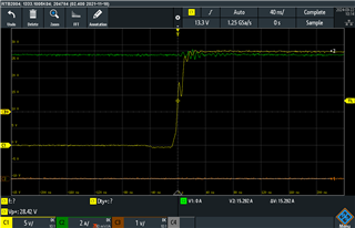
My output is 23V. I am pulsing the output with a period of 20ms and 50% duty cycle

Is suspect it could be some instability?

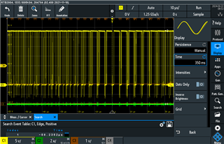
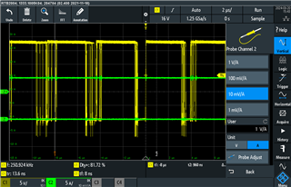
Switch node with a load of 15A

.

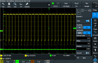
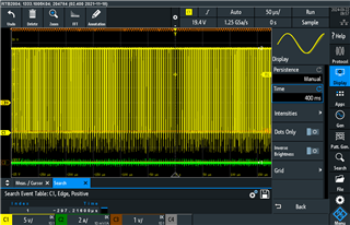
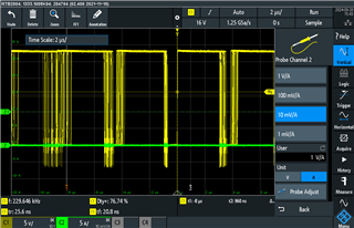
Switch node with no load

Maybe someone could lead my in a direction.

Thank you

  • Hello Thomas,

    Looks like some instability, does not appear normal, can you share your schematic and also be kind enough to fill out design calculator spreadsheet with your requirements so I can check your design against it.

    4251.LM5148-LM25148 Quickstart Calculator.xlsm

    Thanks.

  • Hello David,

    Thank you for the answer.
    I have already used the spreadsheet which I have attached, together with a schematic.

     1614.LM5148-LM25148 Quickstart Calculator_rev3.xlsm

    Thank you

  • Hello Thomas,

    the first thing to try is populating in the design calculator the derated COUT, say to ~50% of what you have.

    then you will need to recompensate and check stability.

    If this does not work, then please note:  spreadsheet does not account for compensation of L202, this maybe the source of your instability.  please short out and retest, thanks.

    Hope this helps,

    David.

  • Hi David,

    Thank you for the suggestions.

    1. Tried to short out this extra 2uH inductor (L202), but that did not change anything.

    2. Used 50% of the populated capacitance in the spreadsheet and changed to compensating components, but no change either.

    But if you say it looks like instability then I guess I just have to play around with the compensating components.

    Another thing to add is that it only makes this click sound when I switch the load ON/OFF. Duing the ON or OFF periode there is no sound.

    Having done some more measurememts, I think I maybe had a bad connection when measuring the SW node. Now it looks more stable, still changing the duty-cycle. I have attached some new pictures of the SW node. 

    Both with no load.

    Thank you.

  • Hello Thomas,

    These waveforms look very normal to me, not sure where the clicking noise is coming from now?  are you sure its the LM5148?  you should be able to see a <20kHz time domain signature in the switch node measurements if its from the LM5148.  please put persistence on and check the jitter, then also look at the output ripple voltage AC coupled, this should show a slight oscillation at <20kZ, if you can see it then I don't believe its from the switching.  

    Hope this helps,

    David.

  • Hello David,

    Try to do some more measurements, which I have listed below together with some measurements details.

    This is where a load is switched ON/OFF and the yellow trace is the output AC coupled.

    Two plots of SW node, with no load and with persistance ON. They look and behave pretty much the same with or without load.

    Output ripple AC coupled with no load.

    SW node rise/fall time under full load of some 14.5A

    All in all I think the switch waveform looks fast and sharp. I have an external 5V supply to VCCX.

    Another point to mention is that the jitter seems lees when I activate 2 channels on my scope, which could indicate something about the sampling as it goes down with the number of channels. My scope is RTB2004 300MHz, 2.5GSa/s which should be plenty fast.

    I hope you can conclude a little more on these plots, if there is an issue?

    Thank you very much and if anything else is needed please let me know.

    Br. Thomas

  • Hello Thomas,

    Transient response looks good, if you can hear audible noise only at low loads may be normal as you are running in Diode emulation mode and PFM at lighter loads, the period of switching will fold back to what it needs to, to regulate output.

    You can check this by enabling device in FPWM mode and check the issue goes away.

    Hope this helps.

    David.

  • Hello David,

    As soon as you mentioned the FPWM, I came to think about the CNFG pin and that I have a 42.1K ohm resistor. This enables the spread spectrum feature. I have now changed this resistor to 27K and the jitter is as good as gone.

    Br. Thomas

  • Thanks Thomas,

    glad you found the source of the audible noise, the output will vary with the frequency of the spsp.

    You are either hearing the noise through the inductor or the ceramic output capacitors.

    Hope this helps,

    David.

  • Hi David,

    Still some jitter on the back slope, but maybe that is normal. I will maybe experiment with the compensation network if this can improve it.

    Yes was also thinking this clicking noise is from the inductors.

    Br. Thomas

  • The responsible engineer is out of office now. The response will be delayed. 

    -EL

  • Thanks Thomas,

    It could be the ceramics also.  I am not sure compensation will help.  but you can give it a try.  Changing output capacitors and/or inductor maybe the way to resolve.

    Hope this helps.

    David.

  • Hi David,

    Yes have now tried to change the crossover frequency and thereby the compensation network, but not really changed anything.

    I will try with your suggestion and play with the capacitors.

    Thank you for support.

  • Hello Thomas,

    Feel free to reopen, if issue is not remedied.

    Thanks.

    David.