This thread has been locked.

If you have a related question, please click the "Ask a related question" button in the top right corner. The newly created question will be automatically linked to this question.

LM25180-Q1: High Active Current Draw

Part Number: LM25180-Q1
Other Parts Discussed in Thread: LM25180, LM5180EVM-S05

Hi TI Team,

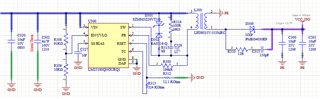
I am using the LM25180-Q1 in my design, I have tried multiple configurations using the CALC tool and also Webench in order to achieve the active current which is mentioned in the datasheet (350uA).

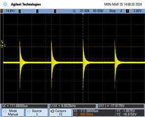
The part is drawing ~1.7mA with no load, when I measure RSET voltage it is 111mV - where this should be 1.2-1.8V according to the datasheet?

My clamp diode is actually 20V part though I have removed these in order to debug the issue and also fitted a 16V clamp, I can't seem to get the current draw as per the specification.

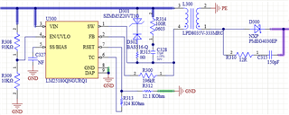
R314 and C328 are DNP. 

  • Total output capacitance is 50uF.

  • Hi Samuel,

    Thank you for designing with the LM25180.  Is your circuit uses a correct RFB resistor?  It should be something like 124k to produce 12V output, but yours is 196k.  Could you double check?  Also, the 350uA current does not include the current through the UVLO resistor divider. 

    Thanks,

    Youhao

  • Hi Youhao,

    I tried with 120k and 130k also and still did not see any decrease in current. Also changed the UVLO/EN divider to 910k and 100k with no improvement.

    The Webench gives an entirely different topology for these parameters - do you know which I should be taking as optimal?

    Thanks,

    Samuel

  • Hi Samuel,

    The Wench most probably uses a different transformer turns ratio: hint is in the RFB. 

    Sorry I forgot to answer one of your earlier question:  VRSET=1.8V in the EC table for I_ACTIVE condition is to force the IC to operate in the min frequency (~12 kHz), which is also the switching frequency under no load.   However, the IC will need a min load to maintain the output regulation, either by a dummy load resistor or output Zener clamp. Therefore, an actual design will have input current always greater than the I_ACTIVE in the datasheet. 

    Could you check if your circuit is operating at 12kHz?  Could you capture a SW waveform?  From there we may get some clue about your issue.

    Thanks,

    Youhao

  • Hi Youhao,

    This is what I see on SW at the moment, looks like 9kHz.

    KR
    Samuel

  • Hi Samuel,

    Thanks.  The frequency looks correct, but the waveform is confusing. How could you get negative SW almost always below GND?

    Anyway, the scope probing is not related to the current draw which your saw earlier.  I got an EVM and ran the test in our lab and I also see ~1.3mA input current under no load condition.  This is mainly caused by the min load condition:  even your load is 0A, once enabled, the IC must switch at the min frequency ( 12kHz typical), and the peak current must reach 20% of Ipk of 1.5A typical, on top of the 350uA Iq. 

    Note that 350uA does not include the min load current.  The 350uA is tested in open loop on our tester without having the flyback transformer installed.

    Hope this clarifies. 

    Best Regards,

    Youhao

  • Hi Youhao,

    Thanks for the quick response on this!

    I think there is something wrong with my probe, or the scope - but there seems to be an offset somewhere but I'm glad you got what you needed here.

    Would it be possible to tell me what the minimum load current achievable is then? I assume that if I include a dummy load resistor I can drive this at minimum load and achieve less than 1.3mA?

    I am optimising my design for sleep current in an automotive setting, and the requirement is unfortunately <1mA.

    If it is not possible with this part by design optimisation, I will have to make another selection for this device.

    KR,
    Samuel

  • Hi Samuel,

    The dump load would not help reduce Iq.   Could we try a different transformer, the 22uH device of the same family (LDP8035V-223)?  Please let me know if you see some reduction of the current at no load.  

    Thanks,

    Youhao

  • Hi Youhao,

    Does the evaluation board use 22uH? And this Iq is 1.3mA?

    KR,
    Samuel

  • Hi Samuel,

    The EVM transformer use 30uH transformer (see below snapshot of EVM BOM presented in the LM5180EVM-S05 user's guide https://www.ti.com/lit/pdf/snvu592), and the Iq is close to 1.3mA.  I think the 22uH would help you to reduce the Iq to below 1mA, and meet your spec. 

    Thanks,

    Youhao