This thread has been locked.

If you have a related question, please click the "Ask a related question" button in the top right corner. The newly created question will be automatically linked to this question.

TPS25831-Q1: TPS25831-Q1 design consideration w/ HD3SS3212-Q1 for 3.3V LDO and current limit mode

Part Number: TPS25831-Q1
Other Parts Discussed in Thread: HD3SS3212-Q1, HD3SS3212, TPS25830-Q1


 Hi E2E team,

I would like to use TPS25831-Q1 and HD3SS3212-Q1 to implement an automotive product. A simplified block diagram is shown below:

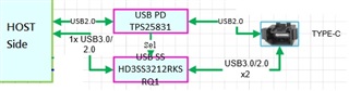
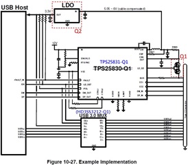
And Its planning is equivalent to Figure 10-27 in the TPS25831-Q1 datasheet.

Initially, I have two questions that I would like to consult:

Q1: There are two modes for current limit. (1)External MOSFET (2)Buck average current limit

       Which one to choose based on what? I didn't find any clear instructions in the datasheet. Maybe I missed something, please remind me.

Q2: In Figure 10-27, a 3.3V LDO as a input power for USB3.0 Mux, and it's input come from TPS25831-Q1.

       Are there any power sequence requirements for this? Since our system already has a buck output 3.3V inside, I would like to use it directly instead of adding another LDO to achieve it.

       Is there anything I need to pay attention?

  • Sorry, let me ask another question.

    Based on datasheet page 4, these 4 pins (A1-A4) seem to need to be connected to PGND and thermal pad.

    However, in the EVB schematic(TPS25831-Q1 Evaluation Module), these 4 pins (A1-A4) are not connect(NC). Could you help confirm which one is correct to follow?

  • Hi Caspar,

    I see that the TPS25831-Q1 is labeled as a USB PD in the first block diagram image you shared. Please note that this device is not a USB PD controller.

    1. The NFET implementation enables the TPS2583x-Q1 buck regulator to supply a 5-V output for other loads during an overcurrent fault condition on the USB port.
    2. No power sequencing requirements to use the HD3SS3212 with the TPS25831-Q1. 
    3. As the datasheet states, A1, A2, A3, and A4 PCB lands should be electrically isolated or electrically connected to thermal pad and PGND, so either one is correct to follow. 

    BR,

    Seong

  • Hi Seong,

    Thanks, I think it should be implemented using TPS25830-Q1. I will inform the system engineer and discuss with him.

    BR,

    Caspar

  • Caspar,

    Sounds good. I will be closing this thread.

    Please start a new one for any other inquiries.

    BR,

    Seong