Dear TI support team,
I am working on building a 1000W (32V, 33A) LLC converter using the UCC256403A integrated controller. I am using a split capacitor half bridge circuit. I am attaching the excel spread sheet with my best working solution so far (at the end of the post).
While using the controller I faced some significant challenges. I hope you can help me out.
First the premise: My LLC converter is a part of a three-stage power supply (PFC, DC/DC (LLC), DC/DC (buck)). Its sole purpose will be to provide galvanic isolation and voltage step down, at a relatively high efficiency. I don’t have any strict requirements on ripple or noise. My major concern is that the converter works in an acceptable manner. Currently I am testing it with a lab source and an electronic dc load – so voltage and load are static – no transients.
My problems: My major problem is that I can not make the converter operate and correctly exit burst mode. My circuit is in a constant bust mode. I load it up to 15A which constitutes around 480W of power, and it still does not exit. Eventually I made the converter exit burst mode at about 3A (100W), but then the output voltage starts to drop – the converter losing regulation (when I increase the output current the converter increases the frequency). Surprisingly enough when in burst the converter regulates the output even up to 15A. Also the sound that the burst mode operation generates is quite loud for output currents above 1A. The attached excel spreadsheets has the solution that exits burst mode at about 3A (burst mode still very load) but the voltage starts to drop.
What I did so far:
- I reduced the magnetizing inductance of the transformer in order to increase the magnetizing current and have steeper frequency/gain curve. This helped me finally exit burst mode – be it at the cost of higher conduction losses.
- I reduced the lower VCR capacitor. At a value of 3.3nF it exists burst quite smoothly, but as soon as it exists the output starts collapsing. If I increase this capacitor slightly, I cannot exit burst for about 10A of output current or at all.
- I tried setting the BMTL and BMTH to 0.2V, either by programing it or by removing the upper resistor of the LL/SS pins. This actually made things worst. My best results are for higher BMTL and BMTH values.
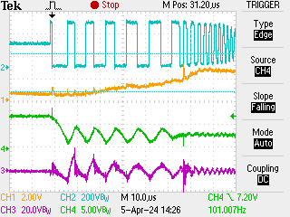
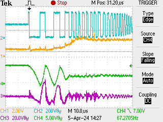
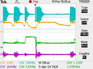
- When in burst mode the converter goes very low in frequency (close to MG(min)) and thus high in peak current for a few periods and then reverts to a pack of high frequency pulses, pause and then repetition. The content of the packs also varies from pack to pack. As I said before when in burst it regulates the voltage correctly even for half of the power of the converter. The converter is very loud.
- When the converter exits burst - it goes silent, it switches into higher frequency, the output voltage starts to drops. When I increase the load, the converter increases the frequency.
- I checked the VCR pin during burst and regular operation. During burst the voltage is all over the place – I guess as the resonant current varies (related to the low and high frequency packs described in 4). During regular operation it’s triangular. Up to 15 amps of regular operation it reaches something between 4V and 5V but – it is not clamped.
- I checked the FB pin during burst and regular operation. During burst the voltage varies wildly. During regular operation is flat. I tried placing and removing a capacitor parallel to the opto-coupler – no noticeable change.
- Based on what I see from the waveforms, the converter, although not optimal, should be on a power electronic basis be able to maintain regulation outside burst between almost no load and full load.
- Output feedback uses the TW103 solution with CC and CV loops. The CC loop is currently disabled (disconnected OR diode). I test in static mode and converter regulates at least in burst – so I guess the feedback circuit is adequate. It tried increasing and decreasing the current of the opto-coupler - results varied.
- I supply the controller and the secondary circuit of the converter using bias supply with two galvanically isolated 15V sources (I don’t draw supply form the auxiliary winding). I have connected the bootstrap supply for the high side driver directly to the controller supply (instead of RVCC). I think I have sufficient decoupling capacitors – 44uF ceramic at the controller supply, 22uF+4.7uF at RVCC, 4.7uF at HS, HB. I haven’t tested the driving circuit.
I hope you can help me out with my predicament.
If you need more information from my side please let me know.
Thank you in advance,
Best Regards
Angel Marinov