TPS25947: Power Good chattering with clean OUT and PGTH

Part Number: TPS25947

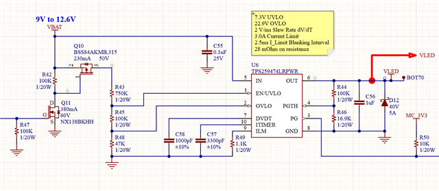
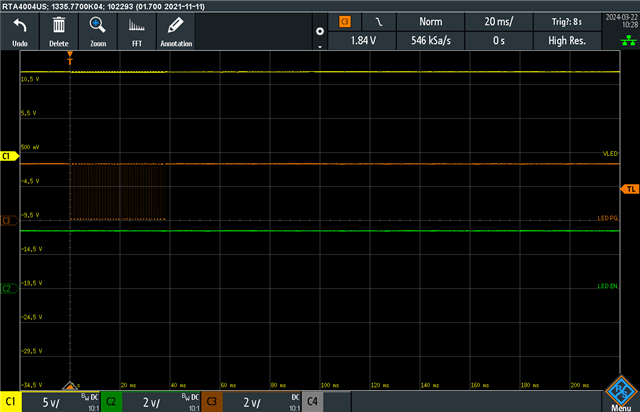
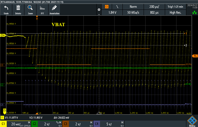
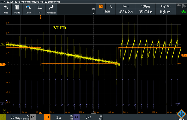
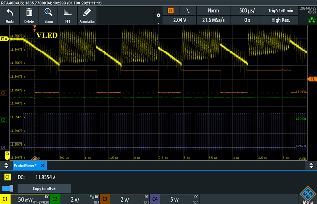
I am testing a circuit where the PG output is chattering when a 3-phase brushless motor is driven from the same board. The motor runs off VBAT, which is also the input to the eFuse. The IN, OUT, EN, and PGTH pins are all clean with no glitches nor dropouts. There are many ceramic bypass caps on VBAT all located close to this circuit. There is no good reason that I can think of for this PG chattering to occur. Any ideas?

  • Hi Dugan,

    I will check and get back by tomorrow EOD on this.

    Regards

    Kunal Goel

  • I gathered some zoomed in traces using my power rail probe to see VBAT at the input and VLED at the output of the TPS25947. 


  • Hi Dugan,

    1. How LED EN is connected to eFuse?

    2. Can we probe pull up supply of PG pin? Lets see if it is fine.

    3. What is the reason for chattering in VIN?

    4. Only possible reason I think could be reverse current blocking(VOUT jumping above VIN)  or overcurrent.

    Regards

    Kunal Goel

  • 1. How LED EN is connected to eFuse?
    LED EN is statically driven to a logic high by a microcontroller. I have confirmed that it stays high and does not glitch nor toggle.

    2. Can we probe pull up supply of PG pin? Lets see if it is fine.
    I have already probed the PG pullup supply and verified that it is stable.

    3. What is the reason for chattering in VIN?
    VIN (or VBAT) is connected to the high side of a motor that is being driven as shown by CH 4 of the scope, signal MOTOR U.

    4. Only possible reason I think could be reverse current blocking(VOUT jumping above VIN)  or overcurrent.
    I think you may be on to something with reverse current blocking since there are caps on VLED that hold it up, but when the motor gets driven, VBAT dips lower than VLED and reverse current will tend to flow. With this hypothesis do the waveforms make sense? Can you describe the eFuse internal circuit functions that are causing the waveforms seen?

  • Hi Dugan,

    It could be VIN falling below VOUT or VOUT jumping above VIN which is causing device to detect reverse current.

    Regards

    Kunal Goel

  • I thought I responded to this but don't see it here now. This line of reasoning that VIN could be falling below VOUT seems likely. The motors are pulling current from VIN while there are caps on VOUT holding up that voltage, and the load at VOUT is light compared to the motor demands. Can you talk to the internal circuits that monitor current flow and how it reacts if negative current flow is detected? I want to understand the mechanisms in play here. Further, have other users encountered this situation and found ways to deal with it?