This thread has been locked.

If you have a related question, please click the "Ask a related question" button in the top right corner. The newly created question will be automatically linked to this question.

BQ25570: TEG design review

Part Number: BQ25570

Hello everyone,

I'm a beginner in electronics design and I'm reaching out to this community for a bit of guidance and advice from those of you with more experience.
I'm working on a project that involves monitoring the temperature of hot surfaces (from appr. 130°C to 190°C) and transmitting this data wirelessly.
I plan to use a STM32 microcontroller paired with an NRF24L01 for the wireless module.
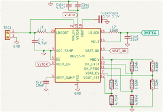
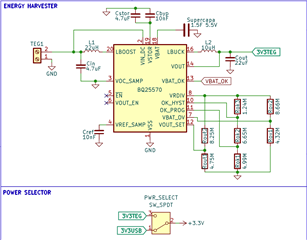
To power this setup, I've designed a schematic based on the BQ25570, incorporating a supercapacitor and a Thermoelectric Generator (TEG). The design closely follows the example given on page 28 of the BQ25570 datasheet.

I've chosen the capacitors and inductors based on recommendations from datasheet, and I've calculated the values for the resistors controlling the nano-power management using the dedicated Excel tool :

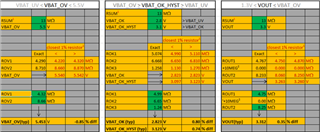
I'm seeking feedback on a few specific areas of my design and would greatly appreciate any insights you could offer:

  1. Could you review my schematic for any potential errors?
  2. I'm unsure about how to determine the appropriate values for VBAT_OK & VBAT_OK_HYST. I've tentatively set these to 2.8V & 3.1V, inspired by other designs, but I'd love to understand the rationale behind these choices.
  3. For the supercapacitor, I'm considering a 1.5F 5.5V model, which led me to set VBAT_OV at 5.45V. Does this configuration seem reasonable?
  4. The datasheet specifies using a "low leakage" Cref. Would a MLCC capacitor like this one [here], be suitable? I know that MLCC have low leakage current but wondering if that's fulfilling the expectation.
  5. I will have a switch to choose from power sources (USB or TEG), seems to be okay to connect/disconnect the load but please allow me to double check this point.
  6. Finally, I'm exploring options for a TEG module. I'm currently looking at a 5V TEG module such as that one [link]. Would this be a relevant choice to use with BQ25570?

I'm eager to hear your thoughts and any advice you can offer.
Thank you very much.

  • Hi,

    Could you review my schematic for any potential errors?

    Just to confirm, based on your schematic you are expecting an MPPT point at 50% of the input open voltage value? Additionally, I recommend tying the /EN and VOUT_EN signals to your preference if you won't be able to control them directly. Better than leaving them floating.

    I'm unsure about how to determine the appropriate values for VBAT_OK & VBAT_OK_HYST.

    VBAT_OK and VBAT_OK_HYST are typically used from over-discharging of batteries for certain chemistries. This can also be used to stop power to the system load if the system is not designed to be powered from below a certain voltage. This is something that is very application specific so I would look at the minimum VSTOR voltage needed to power your application.

    For the supercapacitor, I'm considering a 1.5F 5.5V model, which led me to set VBAT_OV at 5.45V. Does this configuration seem reasonable?

    This is reasonable since the super capacitor should be charged up to about 5.45V.

    Would a MLCC capacitor like this one [here], be suitable?

    An MLCC Capacitor should work for this application.

    I will have a switch to choose from power sources (USB or TEG), seems to be okay to connect/disconnect the load but please allow me to double check this point

    This should be fine.

    Would this be a relevant choice to use with BQ25570?

    That particular TEG would likely not work with the BQ25570 since its open-circuit voltage, according to the datasheet, is 10.8V. So while not loaded the TEG voltage will be set to 10.8V. This shouldn't be used with the VBAT_OV of 5.45V, VBAT_OV should be larger than the TEG voltage. This is because a high input voltage at VIN_DC could cause unregulated charging as the voltage at LBOOST will be higher than the VBAT voltage. This would result in current going through the body diodes of the two FETs that separate LBOOST & VSTOR and VSTOR & VBAT.

    Best Regards,

    Juan Ospina

  • Hello Juan,

    Thank you very much for taking the time to provide me with valuable insights.

    Just to confirm, based on your schematic you are expecting an MPPT point at 50% of the input open voltage value? Additionally, I recommend tying the /EN and VOUT_EN signals to your preference if you won't be able to control them directly. Better than leaving them floating.

    Indeed, as shown in the typical application circuit from datasheet (page 28), MPPT is set to 50% (which is said to be typical for TEG) so I have decided to follow this guideline.
    Concerning EN and Vout, I'm a bit unsure, but according to the datasheet and based on my need, it seems like I should connect VOUT_EN to Vstor and EN to GND, as I reflected below:


    VBAT_OK and VBAT_OK_HYST are typically used from over-discharging of batteries for certain chemistries. This can also be used to stop power to the system load if the system is not designed to be powered from below a certain voltage. This is something that is very application specific so I would look at the minimum VSTOR voltage needed to power your application.

    I am still having difficulties on this point.
    Since I’m using supercapacitor here, I believe that undervoltage protection is not relevant.
    I aim to power the load consistently at 3.3V (no less), and the load is a basic STM32 with an NRF24L01, which are not very power-hungry.

    If I understand correctly, setting VBAT_OK to 3.3V and VBAT_OK_HYST to 3.8V would be suitable for my needs, right?

    That particular TEG would likely not work with the BQ25570 since its open-circuit voltage, according to the datasheet, is 10.8V. So while not loaded the TEG voltage will be set to 10.8V. This shouldn't be used with the VBAT_OV of 5.45V, VBAT_OV should be larger than the TEG voltage. This is because a high input voltage at VIN_DC could cause unregulated charging as the voltage at LBOOST will be higher than the VBAT voltage. This would result in current going through the body diodes of the two FETs that separate LBOOST & VSTOR and VSTOR & VBAT.

    Very clear! Considering the above, it appears that the [TEMP1-0725-0.15] is a better fit for my application:
    http://www.thermonamic.com/pro_view.asp?id=885

    Once again, thank you very much for your support and the time you've invested in my project.

  • it seems like I should connect VOUT_EN to Vstor and EN to GND,

    This would ensure VOUT stays enabled and so does the energy harverster.

    If I understand correctly, setting VBAT_OK to 3.3V and VBAT_OK_HYST to 3.8V would be suitable for my needs, right?

    That should be ok, though 3.8V hysteresis seems a bit high. It would require the Super cap to charge back up to 3.8V to reconnect the load once its been disconnected. If that is suitable for your application then that's fine.

    Very clear! Considering the above, it appears that the [TEMP1-0725-0.15] is a better fit for my application:
    http://www.thermonamic.com/pro_view.asp?id=885

    This should be fine, though I'm curious, how much current would you plan to pull from the TEG?

    Best Regards.

  • That should be ok, though 3.8V hysteresis seems a bit high. It would require the Super cap to charge back up to 3.8V to reconnect the load once its been disconnected. If that is suitable for your application then that's fine.

    Thank you for the feedback, then I'll go with +0.3V : VBAT_OK = 3.3V & VBAT_OK_HYST = 3.6V


    This should be fine, though I'm curious, how much current would you plan to pull from the TEG?

    Based on datasheet, during data transfer : NRF24L01 = 12mA & STM32 =10mA.
    With a confortable safety margin I would say 30mA (100mW) but it is a theoritical value.

    TEG is not chosen yet, if you have a good place to look for or any advices for selection I'd love to hear it.


    Thank you.

  • Thank you for the feedback, then I'll go with +0.3V : VBAT_OK = 3.3V & VBAT_OK_HYST = 3.6V

    That should be good.

    Based on datasheet, during data transfer : NRF24L01 = 12mA & STM32 =10mA.
    With a confortable safety margin I would say 30mA (100mW) but it is a theoritical value.

    TEG is not chosen yet, if you have a good place to look for or any advices for selection I'd love to hear it.

    That would be fine for discharge. With regards to charging, I recommend not going above the 100mA of current range as charge efficiency does go down with higher currents.

    Best Regards.

  • Great, I'll make a PCB to give it a try.
    Thanks for your support Juan!