This thread has been locked.

If you have a related question, please click the "Ask a related question" button in the top right corner. The newly created question will be automatically linked to this question.

TPS7H5001-SP: Unexpected behavior and impedance at CS_ILIM pin

Part Number: TPS7H5001-SP
Other Parts Discussed in Thread: TPS7H5001EVM-CVAL

Hello,

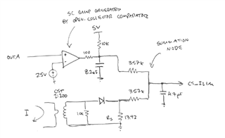
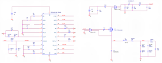
I am currently testing using this PWM in a Buck Converter design. In my design, I have chosen to include slope compensation on top of the current signal external to the PWM chip. I've done this because I would like slope compensation included even when the current limit is encountered.

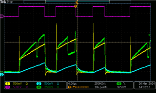
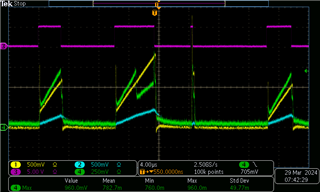
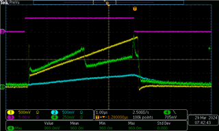
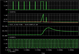
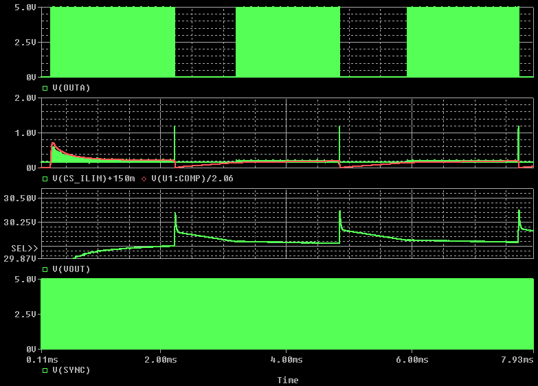
Even though I have included (what should be) sufficient slope compensation to the current signal before it enters the chip, I see subharmonic oscillations at duty cycles near 50%, and see what appears to intermittent, sharp dips in impedance at the CS_ILIM pin (in green, where the current sum waveform has rectangular "bites" taken out of it).

I have tried a range of RSC values for the internal slope compensation, ranging from almost no slope compensation (as none should actually be required, RSC=10M) up to approximately 2x m (.068V/us, RSC=562k).

I always seem to get at least a little subharmonic oscillation accompanied by the weird voltage dip at CS_ILIM (for DC near 50%)

Any light you can shed on this is appreciated. Thanks,
CHAD

Below:
CH1 YELLOW: CST output (prior to summation)
CH2 BLUE: Slope Compensation Ramp (prior to summation)
CH3 MAGENTA: OUTA
CH4 GREEN: CS_ILIM signal (1:1,50% summation of CST and CS Ramp)

  • Hey Chad,

    I'm rather curious about this statement:

    "I've done this because I would like slope compensation included even when the current limit is encountered."

    The slope compensation is subtracted from the COMP pin of the device.
    At no point do we not include it in the control loop.
    Even if you are going all the way to the CS_ILIM threshold, the slope compensation is being subtracted from COMP.

    Certainly the dips in the CS_ILIM pin can cause all sorts of issues for the controller.
    It isn't necessarily an easy test, but you could try and disconnecting the CS_ILIM pin and testing the summation itself.
    The TPS7H5001-SP discharges the CS_ILIM pin node, but should only do so after OUTA goes low.

    Forcing the COMP voltage to like ~1 V and changing RSC to ~30-40 kOhms would do the trick.
    You can start at a lower COMP voltage for a lower duty cycle and slowly increase it to try and get to the right duty cycle value you want to test.
    Something like an open loop voltage mode:
    https://e2e.ti.com/support/power-management-group/power-management/f/power-management-forum/1188134/faq-tps7h5001-sp-how-do-i-use-the-tps7h500x-sp-family-as-a-voltage-mode-controller

    (Don't worry about the ~0.1 V on the CS_ILIM the post talks about for this case)

    Thanks,
    Daniel

  • Thanks Daniel,

    Maybe I am misinterpreting the block diagram. The way it is drawn, it looks like current limit comparator is outside of the Error Amp / Compensator loop. In other words, it looks like whenever the current signal is encountering the 1.05V limit, there is no slope compensation applied to that threshold (as it is in the compensated control loop).

    I first noticed this in test, when I would dial up current output to encounter the limit (with internal slope compensation). For DC near 50%, I would get good operation (no subharmonic oscillation) up to the limit. Then just as I encountered the limit (so the output transitioned from being controlled by the EA output w/ slope compensation to being controlled by the 1.05V limit w/o slope compensation) I would observe subharmonic oscillation.

    This seems to make sense with the diagram, and is why I decided I needed an external ramp to enforce slope compensation even when operating at or beyond current limit.

    Is this a misinterpretation?

    Thanks
    Chad

  • Hey Chris,

    The CS_ILIM threshold will just terminate the output pulse of OUTA.
    The output voltage is not controlled in this mode and depending on the level of the over-current the output voltage will decrease.
    There is no stability and such associated with this mode.

    The CS_ILIM over current threshold is not part of the converter control loop.
    I suppose its correct that the slope compensation is not decreasing the threshold; however there isn't "sub-harmonic oscillations" due to the duty cycle being over 50% because its not a control loop.

    That being said there is certainly a repeating output that is causing an issue, but improper slope comp is not the root cause.

    Thanks,
    Daniel

  • Thanks again for the response Daniel,

    In general I agree that voltage is no longer regulated, but I would argue that there is still a control loop in play that can exhibit subharmonic oscillation. At the point that the current limit is reached (and beyond) I guess I'm thinking just of the inner current-to-Duty-Cycle control loop (no longer tightly controlling to the optimal output voltage, but still able to generate a steady set-point with reduced voltage & current at the output, and still plausibly susceptible to subharmonic oscillation).

    I also agree that what I am seeing (above) is not quite the classic subharmonic oscillation associated with peak current control for DC >= 50%. That may be a little bit of a red herring because the pulse train ultimately ends up looking like it suffers from subharmonic osc., and compounded by the fact that I only see the condition at DC near 50%, and that it's character changes somewhat (but does not go away) as I adjust the internal slope compensation (RSC).

    Can you provide any additional information on what occurs when (and how) the CS_ILIM pin is pulled down? For whatever reason, it does appear (above) that it is getting pulled down in the middle of the OUTA pulse, and then returning, without the actual OUTA pulse transitioning or truncating (if that is possible). Below is a similar capture during nominal operation (DC approx 25%). I see that the CS_ILIM voltage is pulled low at the end of the OUTA pulse (which appears to be nominal, and is not problematic).

    Thanks again,
    Chad

  • Hey Chad,

    There is a small uA discharge circuit that turns on after OUTA is low.

    I would suggest investigating with the current sense disconnected to confirm what is going on.

    Thanks,
    Daniel

  • Thanks Daniel,

    After doing some more testing, I noticed that the strange CS_ILIM voltage jumps also was occurring well below 50%DC (further cementing that this is not a slope compensation issue). That said, adjusting the RSC does appear to have an effect on this anomaly.

    Below is a capture at approx. 30%DC (still closed loop) with what appears to be a voltage step being induced on CS_ILIM. (In this shot CH3 MAGENTA is COMP voltage, roughly indicating where the CS_ILIM signal should intersect and end the OUTA pulse).

    I proceeded to disconnect the CS_ILIM pin to observe the current and summation waveforms in an open loop configuration. (See below). I ran the open loop configuration at about 30%DC and got completely clean waveforms. Notice also that the green summation waveform lacks the "pull-down" that was apparent (presumably from CS_ILIM pin) at the leading & tailing edges above.

    It certainly appears like the CS_ILIM uA discharge is being activated (at the correct time judging from the first capture) but without OUTA actually turning off (if that is a possibility).

    I notice on the second capture that there are some small transients on the green sum waveform that line up OUTA transitions (but not the subsequent delayed FET transitions), but that may be probe crosstalk.

    Thanks again for any input you can provide,
    Chad

  • Hey Chad,

    Its possible there is noise getting in to the controller and causing this issue.

    Do you have a schematic available to share?
    I need to talk with my designers to see which pins might be the most susceptible to causing this issue.
    (from my experience noise likes to couple into DCL and HICC from the SYNC pin, but I havent seen it do this before)

    Thanks,
    Daniel

  • Sure Daniel,

    See schematic below. The ramp generator (comparator) is drawn in, as that is a part of the circuit that has been white-wired in during development.

  • Hey Chad,

    Is the LEB resistor R221 correct?
    That is well higher than anything I have seen for that resistor.


    Could you try a ~10-100 kOhm or some such value?
    Those are values we test as per the electrical characteristics.

    Thanks,
    Daniel

  • Daniel,

    Yes the RLEB resistor (R221) is currently selected at 432k. This is above the datasheet recommended maximum of 300k. I had arrived at the 432k value after our conversation here, and determined experimentally that the 432k value resulted in a LEB of 420ns (which was desired at the time).

    Per your suggestion (and because that large LEB is not strictly necessary due to the current filtering configuration) I have reduced the RLEB to 100k. The CS_ILIM glitch persists (see below).

    Noticeable now is that the Leading Edge spike is now unaffected, whereas before it looked like CS_ILIM was suppressing it (plausibly expected behavior during LEB). Perhaps there is a clue in this: before adding the new summation circuit, with its increased impedance in the signal path to CS_ILIM, there was not observable suppression at the leading edge (I was only able to confirm LEB via the method described in the linked discussion). Perhaps this increased impedance is playing a role in "tricking" the decision-making and turning on the uA discharge but without terminating the OUTA pulse? [It appears from the capture below (and has been consistent in my testing so far) that the point where the glitch occurs is where the OUTA pulse should have been terminated.]

    Thanks
    Chad

  • Hey Chad,

    I discussed with my designer and found that the trigger for the current pull looks for 2 things:
    1) There is a transition for one of the outputs to go low
    2) That the device isn't in LEB.

    This is connected to the VLDO rail, so make sure there isn't too much noise on that, you can also check if OUTB is somehow on, but that doesn't seem too likely.

    If your assessment is correct and OUTA is not transitioning low for some reason I would worry about something internally being damaged.
    This is easy enough to check by probing COMP/CS_ILIM and looking at where they approximately cross.

    Thanks,
    Daniel

  • Hi Daniel,

    I had a chance to replace the TPS7H5001 chip (to rule out damage) and the anomaly still occurs.

    An interesting note is that is happens very consistently at low loads (for instance, the rogue pulse occurs right at about 2.5kHz with a light load of approx. 0.25A). At higher output levels, it will still occur, but much more spuriously, maybe only once or a few times per minute.

    Below the converter is running with output current approx. 0.75A:
    CH1 YELLOW: CS_ILIM
    CH2 BLUE: VOUT
    CH3 MAGENTA: OUTA
    CH4 GREEN: COMP

    As mentioned before, it looks like at the decision point where CS_ILIM = COMP/2, the micro-amp drain response turns on (puling down on the CS_ILIM signa), but the pulse does not terminate. Then the CS_ILIM plows right on through the COMP/2 signal, again without terminating the pulse. It's not obvious what causes the pulse to terminate, but it appears to be right around 50% duty cycle (this has been observed for previous rogue pulses as well).

    I will take a look at the VLDO rail for noise and look at OUTB as well to look for strange behavior.

    Thanks
    Chad

  • Hey Chad,

    The fact the pulse doesn't terminate when CS_ILIM continues past COMP is rather concerning.
    As far as I am aware the only situation that can happen is during LEB of the device.

    Given the sporadic nature of the occurrence it seems logical to believe something in the circuit/layout is adding noise internally to cause this.
    Most internal noise issues are solved by decreasing the RSC resistor, though this issue seems like it wouldn't care about it.

    Thanks,
    Daniel

  • Yeah, the whole thing is very perplexing.

    I look a look for activity on OUTB (CH4/Green Below) and did see some very small blips associated with FET turn-off. But nothing in the vicinity of the rogue pulse glitch.

    I also took a look for noise on the VLDO & DCL pins (CH4s/Green, below), they looked clean to me (no noticeable noise associated with FET switching or otherwise).


    This search for noise effects brings up another observation however: the rogue pulse glitch appears at a point when no switching (On or Off) occurs. In other words: it seems hard to blame the glitch on noise if it is occurring (only) during the quietest intervals.

    Thanks again for any input,
    Chad

  • Hey Chad,

    Noise sources can be from quite a few things and not all of them obvious.

    I would be interested to see you put a large amount of capacitance on HICC (3.3 nF or higher)
    We have found in the past SYNC to be a large contributor of noise that can propagate from the HICC pin to other parts of the device.

    Thanks,
    Daniel

  • Daniel,

    Fair enough (re:noise). I was focused on the converter switching noise being the primary concern here, but I agree that may not be the culprit. I have installed a 100nF cap at the HICC pin (was previously tied to AVSS via zero ohm jumper). The rogue pulse glitch is still occurring.

    Your comments on LEB & the SYNC pin signal I think maybe have implications for the symptoms (if not the root cause).

    It certainly looks like the LEB function is being activated at what should be the OUTA pulse termination point, as indicated by the pull-down on the CS_ILIM signal, and the comparator "ignoring" of the signal intersection (and overrun) of the COMP/2 signal. Then it looks like the LEB function is terminated at the rising edge of the next SYNC clock pulse (I've scoped that below), at which point the pull-down on CS_ILIM is released, and the OUTA pulse is terminated, presumably because the comparator is no longer ignoring (or being ignored).

    So (just from the behavior) it seems plausible that LEB is erroneously being activated, then terminated. I currently have the RLEB at 10k (minimum advised by datasheet).

    Having no visibility of the mechanism(s) that drive the LEB function, I'm not sure how or why layout could cause this, but I could certainly provide some of my layout artwork if you think that would help diagnose the cause.

    -Chad

    CH1/YELLOW: CS_ILIM
    CH3/MAGENTA: OUTA
    CH4/GREEN: SYNC

    IOUT = 7.0A, CCM duty cycle

    IOUT = 6.0A, CCM duty cycle

    IOUT = 2.0A, DCM duty cycle

  • Hey Chad,

    I can certainly comment on layout and what might cause issues, but I doubt I'll be able to point to the exact issue you are running into.
    The way to test for noise is generally just start adding cap/isolating signals until you find positive changes.

    Separate note, if you probe LEB at the same time as everything else does the issue go away?

    Thanks,
    Daniel

  • Thanks Daniel,

    Probing at LEB did not have noticeable effect on the issue. Putting a probe on RSC did however improve things. The issue has not gone away entirely, but it's frequency reduced and it's characteristic changed somewhat. (I picked RSC because in previous testing it's value did appear to have some effect on this anomaly, it's current value is 1.562M).

    The rogue pulse was most consistent at light load (where I was trying to observe pulse skipping). That is still true, but the magnitude of the pulse is now greatly reduced (approx. 2.5us instead of the 5.0us observed before) and it no longer has an "obvious" release of the CS_ILIM pull-down. (it is clear below that, when compared with a nominal pulse, the rogue pulse is being affected by the pull-down).

    The capacitance of these probes is pretty small (on the order of 2pF).

    It seems that it may be worth while to test with some capacitance installed on RSC (and perhaps other places). Do you have a recommendation for a maximum capacitance to install here? (I was thinking of starting with 10pF).

    Thanks
    Chad

    Rogue Pulse

    Nominal Pulse

  • Hey Chad,

    I would keep the capacitance as low as possible (10 pF seems fine)
    I would avoid anything outside of pF in the case it messes with something during start up since the chip expects a stable current.

    It does seem like you found where the noise is getting into.
    It may be beneficial to look for noise sources close to the pin.

    Thanks,
    Daniel

  • Hi Daniel,

    I continued to investigate this, but was never able to eliminate the issue by adjusting impedance at the RSC pin. 

    What did ultimately make the issue go away was changing DCL from 100% to 75% (a max DC of 75% is sufficient for my design, so this workaround is essentially trivial).

    In order to test if this issue was due to my layout, I wired a PWM eval board (TPS7H5001EVM-CVAL) into my converter so that my PWM (and it's layout) would not be used at all. The rogue pulse issue appears to persist (see below).

    Is there a clue in this finding (the link to DCL) that points toward a broader workaround that would allow operation with DCL = 100%? If not, it appears to me that this PWM is not able to operate reliably at duty cycles greater than 75%. The issue appears most persistent at light loads when pulse skipping occurs.

    Thanks
    Chad

    Eval PWM, DCL = 100%

    Eval PWM,. DCL = 75%

  • Hey Chad,

    We can look more into the internal of the part to see more of what is happening.

    I would suggest moving forward with the fix you found if it is trivial.

    Thanks,
    Daniel

  • Daniel,

    The thing that concerns me about the workaround is that it's mechanism is unknown (for the time being). It's not clear if the issue is really solved, or if I have nudged operation into a nominal edge case (from which I might return for equally unknown reasons).

    Another interesting artifact to that end: I am seeing this issue now also being demonstrated in a Pspice simulation using the PWM spice model (see below). This would seem to bolster the notion that this is not a result of noise versus a suboptimal layout. In simulation however, the issue crops up for both DCL = 100% and DCL = 75%, which has me a little worried about the workaround.

    Thanks again,
    Chad

    Pspice simulation:

  • Hey Chad,

    Yes we will need some time to investigate this.

    The problem may simply be the way the current sense is done then, because how you did the current sense is something that was never tested with the part.

    If the issue is showing up in PSPICE I would be interested in looking into it there because thats a bit easier to test.

    See attached for how to share the files.
    https://e2e.ti.com/support/tools/simulation-hardware-system-design-tools-group/sim-hw-system-design/f/simulation-hardware-system-design-tools-forum/969692/faq-pspice-for-ti-how-do-i-share-pspice-for-ti-projects#:~:text=The%20best%20way%20to%20share,following%20checkboxes%2C%20then%20click%20OK.

    Thanks,
    Daniel

  • Daniel,

    I actually reverted the current sense scheme to the previous (simple, filtered current sense transformer) design and the issue still occurs. Similarly, the Pspice simulation that exhibits the same behavior is without an external slope compensation or summing circuit. So I'm not convinced that its my variation on current sense that is causing this.

    For some reason I'm not able to archive the Pspice project without Pspice crashing. However, it's not a terribly complex schematic (see below, it's a modification of the Pspice Buck project available for download from the TI website).

    The rogue pulse seems to occur right around when the COMP/2 signal approaches 200mV (from above or below), not sure if that's a clue. The behavior seen in the simulation is remarkably similar to what is observed in the lab.

    -Chad

  • Hey Chad,

    I will attempt to recreate the schematic and see the issue.

    Thanks,
    Daniel

  • Hey Chad,

    I have confirmed that the reason you see the issue in the model is because of the revision of the model you are using.
    We were able to recreate your issue in Rev (B) of the model, but not Rev (C)

    The update from RevB to Rev C fixed a 20 ns mismatch between two internal clocks.

    As to how this relates to your issue in lab, it would relate back to noise in the set-up.
    Our thoughts would be that noise could possibly cause a similar issue.

    Thanks,
    Daniel