This thread has been locked.

If you have a related question, please click the "Ask a related question" button in the top right corner. The newly created question will be automatically linked to this question.

UCC25800-Q1: UCC25800 with multiple winding planar transformer.

Part Number: UCC25800-Q1
Other Parts Discussed in Thread: UCC25800

Hi

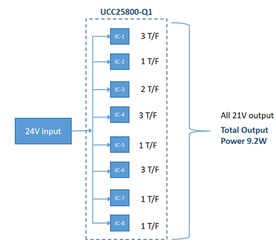
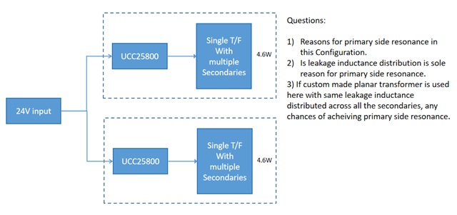
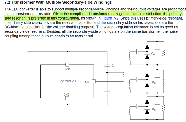
I wanted to go with a multiple secondaries approach, where my previous design is distributed one, I wanted to know that from the highlighted text that

1) Is there any hardware change needed for centralized architecture (except OCP setting), from the attachment I can see that the resonant capacitor role get transferred to primary side capacitors? If hardware change is needed do mention the same in your answer.

2) And If I can manage to design my transformer with leakage inductance equally distributed among all the secondaries then the resonance will be on the secondary side? Since I want to keep the voltage regulation tight.  are there any other parameters to take care of to maintain the resonance on the secondary side even with multiple secondaries?

3) Any chances of achieving secondary side resonance with Planar transformer having multiple secondaries?

  • Hi,

    Let me first clarify with you that (1) the transformer has one primary side winding and several secondary side windings and all these windings on the same core - if this is your transformer structure then you cannot get get secondary side resonance and you can only design with primary resonance.

    (2) what do you mean no hardware change? Is your total power the same or different when you change from single secondary to multiple secondary? Are you using single transformer or parallel several transformers?

    To understand your converter structure please provide your converter system of ucc25800 diagram to show what you want to do as I am not clear and can interpret your words possibly different from your thoughts so a diagram would be needed to understand your mind correctly.

  • Hi, understood the difficulty in understanding my thoughts here I tried addressing them with a diagram. please comment on the same

    Previous design

    Current design thought

  • Hi,

    Each ucc25800 has its own primary side resonance, you cannot get the secondary side resonance because of the transformer winding coupling the resonance cannot be done separately on the secondary side, as one secondary resonance done does not mean all secondary done so these will be on the primary by coupling unless all secondary resonance can be done exactly at the same time which can only be in theory.

    So each ucc25800 has its own primary resonance. If you want to have the with the same resonance the two ucc25800 needs to have f sync and with identical transformer leakage inductance and resonant capacitance so practically not possible. But with f sync the operation should be close each other.

  • Thanks for the reply Hong.

    Please explain me the highlighted text, my understanding is like this " Because of uneven distribution of leakage inductance it is preferred to use primary side resonant configuration" Correct me if I'm wrong, I'll post my query in step by step so that I'll get the information what I'm looking for.

  • Hi,

    The transformer with several windings on the same core, all these windings coupled each other so not able to distinguish when one winding resonance complete - the resonance complete due to all windings. So each individual secondary resonance cannot be clearly defined. It is not only unevenly distributed leakage but also all windings on the same core tightly coupled to each other which make the resonance as a whole so cannot separate each.

  • Thanks, how about primary side resonance, I can see that it will give voltage regulation issues, how bad it can go, I'm looking for 3W application with 21V as my output voltage.

  • Hi,

    The primary-side resonance is ok as all secondary-side leakage inductances are reflected to the primary-side leakage inductance to make the resonance on the primary-side.

  • how to choose them If I want my resonance frequency to be <250kHz (Lr = 2.25uF referred to primary side) , Can I use 0.1uF caps (0.2uF as total I'll get the Fr = 237kHz)

  • Hi,

    What is the capacitance Cr in your design based on Equation 17? After you get the capacitance, Cr, then the DC blocking capacitance, then the DC blocking capacitance at least 10x Cr, or minimum 1uF, and pick up the bigger one between these two.