A related question is a question created from another question. When the related question is created, it will be automatically linked to the original question.
If you have a related question, please click the "Ask a related question" button in the top right corner. The newly created question will be automatically linked to this question.
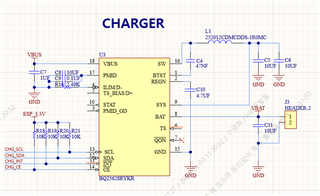
-Unless you are planning to set TS_IGNORE = 1 (REG0x1A bit 7) to ignore TS pin feedback TS pin needs to be connected as shown in figure 8-3 on page 23 of the datasheet. The datasheet provides an example for RT1 and RT2 calculation. Although if you do not plan to connect a thermistor for battery temperature monitoring then TS pin can be connected between the following resistor values RT1 = 10kohm and RT2 approx. = 8kohm.
In summary if you plan to set TS_IGNORE = 1 then TS and TS_BIAS pins can be left floating.
-Pin 3 on the BQ25628E is PG (power good indicator) not PMID_GD. It is a status output. If you do no wish to use it can be left floating.
The rest of the schematic looks okay. I do not see any clear issues.
Please explain as an example of the input current limit setting of the ILIM pin.
Input current limit is set by both ILIM pin and IINDPM register setting in REG0x06. The actual input current limit will be the lower value between register setting and ILIM pin setting. In the provided schematic the ILIM pin sets input current limit to approx. 1A. You mention this is for a 2A charger design. Therefore you likely want to reduce the ILIM resistor to approx. 1.2kohms to set input current limit just above 2A.