This thread has been locked.

If you have a related question, please click the "Ask a related question" button in the top right corner. The newly created question will be automatically linked to this question.

LM5152-Q1: How to check Phase Compensation and Gain margin in LM5152-Q1 PSpice Transient Model (Encrypted)?

Part Number: LM5152-Q1

Hello Texas Instruments

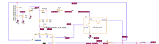
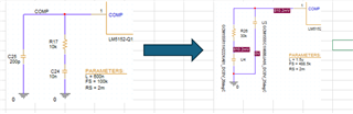
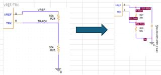
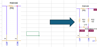
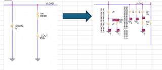
 I am using LM5152-Q1 Pspice Transient Model which changed MOSFET , resister , capacitor and inductor. 

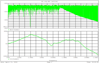
I want to check Phase Compensation and Gain margin in my simulation model .

Could you please show me  how to check?

regards  Takeshi

  • Hello Takeshi,

    Thanks for reaching out to us via e2e.

    For the creation of a Bode plot you will need to use the AVERAGE model which you can also download from our website:
    www.ti.com/.../slvmdu9

    Either use the test bench that comes with it, or go to simulation settings and select "AC Sweep/Noise"
    Select "logarithmic decade" and enter Start / stop frequency and resolution of the simulation.

    Outside of a PSpice simulation, you can use the QuickStart calculator which you will find here:
    www.ti.com/.../SLVRBL5


    All information in this correspondence and in any related correspondence is provided “AS IS” and “with all faults” and is subject to TI’s Important Notice (www.ti.com/.../important-notice.shtml).

    Best regards
    Harry

  • Hello Harry

    Thank you very much for your reply.

    Please tell me about Average model .

    what is  Vsupply pin? Is this Bias pin?

    If this pin is Bias pin, is it  possible to connect Vload?

    In my design,I connect Bias pin to Vload.

    So,I  connected Vsupply pin to Vload and simulate.but it seems wrong result.

    Best regards

    Takeshi

  • Hello Takeshi,

    The average model is a very simplified model of the device, and the only purpose is the simulation of the feedback loop and the generation of a Bode plot.

    It cannot be used to model your actual application.
    Therefore, please do not modify the topology / supply, etc.
    Only modify components which are relevant for the feedback loop (compensation network, inductor, output capacitors, etc.)

    If you connect the supply to VOUT, then - in this particular model - you will also feed the error signal into the supply which gives you bad results.

    Therefore, please ignore where your supply of the controller IC is connected in your real application and do not modify this in the average model.
    In reality, this is just an input to the internal regulator, so for the generation of the Bode plot, it is not important where the feed for this pin comes from.

    All information in this correspondence and in any related correspondence is provided “AS IS” and “with all faults” and is subject to TI’s Important Notice (www.ti.com/.../important-notice.shtml).

    Best regards
    Harry

  • Hello Harry

    Thank you very much for your reply.

    please let me confirm  below  5changes.

    (1).Is it possible to use real component library? for example, like this

    (2)Is it possible to add capacitor like this?is this topology change?


    (3)Is it possible to add resister?is this topology change?

    (4)Is it possible to change like this?

    (5)Is it possible to change Vsupply 5V ⇒ 6.5V?

  • Hello Takeshi,

    From my personal point of view, the average model is made to verify the changes of most of the components that you have listed.
    But there is no switching going on in that model, so some chnges like the current sense filter may not make sense there.

    I have forwarded your questions to a colleague. He will get back to you at the beginning of next week.

    All information in this correspondence and in any related correspondence is provided “AS IS” and “with all faults” and is subject to TI’s Important Notice (www.ti.com/.../important-notice.shtml).

    Best regards
    Harry

  • Hi Takeshi,

    Thanks for sending the detailed questions.
    Here are my replies:

    Q1. Yes, you can use real components library parts.

    Q2, Q3, Q4. Yes, you can add those changes to create a simulation that is closer to your physical board structure. This should improve the simulation accuracy.

    However, please keep in mind that the result will still be a simulation. The simulation models provided by TI are meant as design assisting tools to estimate the real board behavior. Even if the simulation shows good stability behavior, I would highly recommend to measure the stability on the physical board.
    A physical measurement will show the influence of layout, board noise and interference, which cannot be simulated in this PSpice model.

    Best regards,
    Niklas

  • Hello Harry & Niklas

    Thank you very much for your reply.

    I understood that all quiestions is no problem.

    I close this quiestion.

     Best regards

    Takeshi