This thread has been locked.

If you have a related question, please click the "Ask a related question" button in the top right corner. The newly created question will be automatically linked to this question.

LM5022: startup delay observed in LM5022 flyback design

Part Number: LM5022

Hi TI experts,

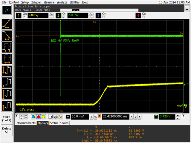
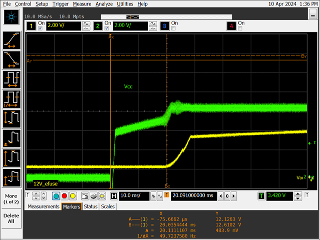
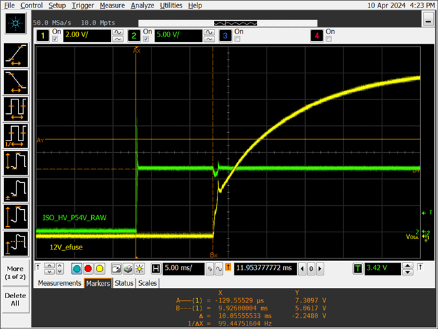
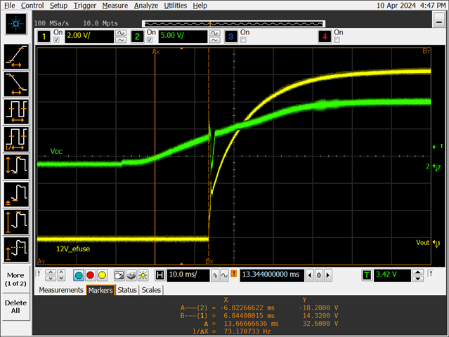
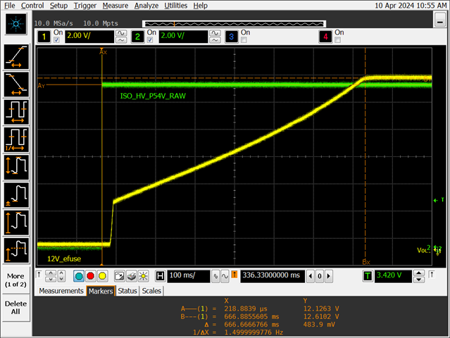
For LM5022 based flyback design, we measured there is about 20ms delay from Input ramps up to Vout starts ramping.

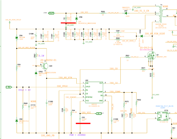
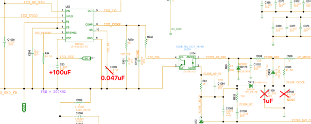
Can i know why there is a delay?

How can we reduce the delay?

Thanks.

Input and output waveform:

Green is input voltage, Yellow is output voltage.

Zoomin waveform

  • Hello Neo,

    Thanks for reaching out to us via e2e.

    There is nothing inside the controller which would create a 20 ms delay, so there must be something wrong with the external circuitry.

    One idea that I have in case of a flyback design is that the VCC capacitor cannot be charged within reasonable time.
    Either it is too big or has too much leakage or some external auxiliary supply for the VCC pin may consume the current, so that the capacitor cannot get properly charged.

    Similarly, if there is too much leakage on the soft start capacitor, the controller cannot start.

    Please also check if the UVLO, VIN, COMP and FB pin voltages are correct.

    All information in this correspondence and in any related correspondence is provided “AS IS” and “with all faults” and is subject to TI’s Important Notice (www.ti.com/.../important-notice.shtml).

    Best regards,
    Harry

  • Hi Harry,

    If you see below VCC waveform (green), it is charged to ~6V when Vout starts ramping, is this expected?

    Also, looks VCC is charged slowly in this period. 

    In schematic there is a 10uF+1uF on VCC pin.

    From schematic, do you see anything abnormal?

    Today, i also tried to reduced primary SS cap from 470nF to 47nF, and secondary SS cap from 100uF to 1uF, and add extra 100uF on VCC pin.

    The voltage ramp up looks faster but observed glitch during Vout ramping up, a big voltage glitches. Can this be fixed?

    Also, one question, if VCC is alway active (e.g powered by external source), when VIN ramps and cross its UVLO, will flyback Vout starts ramping immediatly?

    Thanks.

    Neo

  • Hello Neo,

    Yes, it is expected that the VCC voltage first needs to exceed that threshold, before the device will start working and initiate the SoftStart sequence,

    But, the VCC voltage should not ramp that slowly. This is what is causing your initial delay of 20ms.

    Is the Vin voltage on pin 1 also ramping like that? There is that internal regulator which limits the VCC to about 7V.
    As long as Vin is lower than that, VCC will be about 200mV lower than Vin.

    I would propose removing all external extra components and feed the Vin pin with an external supply to find out where the problem comes in.

    Regarding the SoftStart capacitors:

    There must be a capacitor connected to the SS pin, but it will not limit / slow down the ramping of the output voltage. Using 47nF should be fine.

    When you reduce the secondary SoftStart that much, you will end up with the instabilities that you see.

    Here is a document that describes, how the voltage on the (primary) SoftStart capacitor can be utilized - by adding an external transistor - to limit the voltage on the COMP pin (see chapter 4.4.1):
    https://www.ti.com/lit/pdf/snvaa44 

    All information in this correspondence and in any related correspondence is provided “AS IS” and “with all faults” and is subject to TI’s Important Notice (www.ti.com/.../important-notice.shtml).

    Best regards
    Harry

  • Hi Harry,

    Do you mean we should use below Figure-9-8, not Figure-9-9? Can figure 9-8 ensure a smooth startup?

    If go with Figure 9-8, which value can be used for primary SS cap?

    Thanks.

    Neo

  • Hello Neo,

    I am sorry, my previous description was obviously not precise enough.

    In a flyback converter, the output voltage will start from 0V (not from Vin like in case of a Boost converter).
    But the LED of the opto-coupler will need something aound 2V to be able to work.
    Therefore, in the beginning, the feedback via opto-coupler cannot work and you will see this spike.

    The external transistor, as shown in figure 9-8, will help to avoid this spike.

    You can try to get around without the secondary side Soft Start, but due to the non-linear characteristics of the transistor this will not really work nicely.
    So, I would recommend using both methods in combination.

    All information in this correspondence and in any related correspondence is provided “AS IS” and “with all faults” and is subject to TI’s Important Notice (www.ti.com/.../important-notice.shtml).

    Best regards
    Harry