This thread has been locked.
If you have a related question, please click the "Ask a related question" button in the top right corner. The newly created question will be automatically linked to this question.
Hi,
We need to use the LM5146 for our new design, and the parameter 36VDC input voltage, and output voltage is 28VDC and output current is 8A,
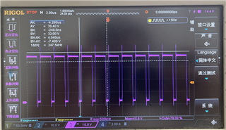
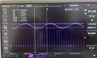
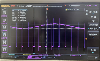
And now, we use the LM5146-Q1-EVM12V to simulate our circuit, but we test the EN voltage=3.36V , VCC=1.99V, VOUT=0.025V;
and if we want to implement our parameter requirements, how to design the circuit.
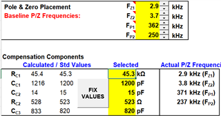
Please use the LM5146DESIGN-CALC to share us how to fill out this excel, thanks.
Hi Zhang,
You can use the LM25145 (42V) or LM5145 (75V) here instead of the LM5146 (100V). Go ahead and fill out the quickstart calculator, and I will review it.
For the EVM, note that the 12V output is tied to VCC, so this needs to be disconnected if you adjust Vout to 28V . Take a look at the application examples in the LM5145 datasheet in particular - there is a 24V output example that may be relevant.
Regards,
Tim
Hi,
Please review the quickstart calculator that we use the LM25145:
8233.LM(2)5145, LM5146 contorller design tool - revA1.xlsm
Now, we use the LM25145 instand the LM5146 on the LM5146-Q1-EVM12V(we consider the LM5146 is P2P to LM25145),
and we test the input voltage=36VDC, and output voltage=28VDC and output current=6-8A,
1. We set the output current=6A, the SW waveform is well;
2. We set the output current=8A, the MOSFET and inductive temperature are rise to 80℃, and the waveform is abnormal:
We consider it is the control Loop Compensation issue, and we don't know how to set parameter, can you kindly help to provide your suggestion to solve
the MOSFET temperature rising and waveform abnormal issue, thanks?
Zhang,
The specifics for voltage-mode compensation in terms of pole and zero placement, etc. are given in the LM5145 datasheet.
In terms of the quickstart, what is critical is accurately setting the output cap value. Note that ceramics derate significantly with voltage, so with Vout = 28V I assume you're using 10uF/50V ceramics - the value will be about 30% of nameplate at that voltage - check with the Murata simsurfing online component tool.
Here are additional comments on the quickstart:
Regards,
Tim
PS: also check input filter damping here, especially if the filter inductance is high. The best way to damp it is to place an electrolytic cap across the input ceramics, where Cdamp = 4*Cin(ceramic) and Rdamp = SQRT(Lin/Cin)
Hi Timothy,
Please kindly help if we need to output is 28V/6A solution, and we need to set the pole and zero placement, can you help to promote the appropriate parameters? Thanks.
Zhang, what are your output cap part numbers? Once you enter the effective Cout and ESR in the quickstart, it will give compensation values for a given crossover frequency target.
--
Tim
Hi Timothy,
Our output capacitor part# is Wurth Electronix 885 012 109 011(47uF*6) and 885 012 206 071(0.1uF*1), the datasheet please refer to below:
Thanks, Zhang.
The 0.1uF doesn't really impact the total capacitance, but go ahead and check the capacitance derating of the 47uF/16V part. Note it's only X5R rated to 85°C, so it may have even more derating than an X7R.
More important, this is only a 16V rated cap and Vout is 28V. I recommend you change to 10uF/50V/X7R/1210. Even the 0.1uF cap is only 25V, so there are gross errors in component selection here.
--
Tim