This thread has been locked.

If you have a related question, please click the "Ask a related question" button in the top right corner. The newly created question will be automatically linked to this question.

LM5164-Q1: Low Current Operation

Part Number: LM5164-Q1
Other Parts Discussed in Thread: LM5164, LM5013, LM5165

I need to use the LM5164 with a load that has 2 modes of operation:

700mA normally and 80mA while in standby.

While there are no design issues for the 700mA load, the Excel Design Tool shows an error when entering a load of less than 100mA.

To be more precise in the explanations it is clearly stated that the cell will become red when entering a value less than 100mA.

I see no explanation about minimum current load in the data sheet.

Reading other threads I found the referenced one, where the option to use a separate Ron but it seems this is not what will solve the problem.

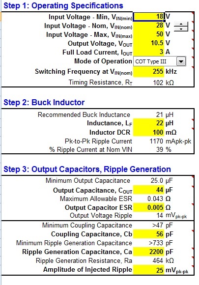
Increasing the frequency requires a different inductor and ripple generation resistor.

To make the long story short, can the LM5164 work with low current? And if yes, how can I do it for the 2 current levels.

  • Hello Emanuel,

    As you mentioned the cell just goes red if the amount of load current entered<0.1A.

    This device is a 1A device and the current limit is set to 1.5A typ, so ILIM is much higher for a load current that is so low. 

    With that said, this device will work for low load currents without issues.

    However, you need to make sure the inductor used is rated for the max peak current limit internal to the device.

    Hope this helps.

    David.,

  • Hi David,

    Thank you for your answer.

    Indeed the Excel shows the current range error if <100mA but the calculator still works and shows a very high inductor value for the low current.

    I recently used the same IC in a different project, also with 700mA nominal load at approx. 250kHz. In the conducted emissions test I noticed the clear peak at this frequency but the same circuit was also used at half that current, 350mA and I noticed that the frequency dropped to about 130kHz, also half.

    The question is how much it will drop for 80-90mA, if possible at all.

    If the internal current limit is the problem I can switch to LM5013. 

  • Hello Emanuel,

    It's not an error, it's more of a caution.

    I assume you mean the switching frequency.  As such you will get a noise spike at that frequency in the EMI.  if you design the converter with a high enough value inductance, there will not be a drop in switching frequency.  Depending on the inductor selected, if you run into DCM mode, there will be a low frequency component to the switch node that will show up in the EMI Profile.

    Regarding the LM5013, yes, you can use this device.  another device to consider is the LM5165.

    Hope this helps.

    David.

  • Hi David,

    Perhaps I will give you the full "picture".

    I am working on an automotive lamp with 2 strings of LED, each string with its own DC-DC stage followed by a linear driver.

    One string works on 0.7A the other has 2 modes, 0.7/0.35A. As I was concerned about having both oscillators set at the same frequency I adjusted the first at 260 kHz and the second to 240kHz. The voltage is slightly different as the first is 4 red LEDs and the other is with white LEDs.

    The settings are shown in tables 1 and 2 on the Excel screenshot below.

    The first one works perfectly and in conducted emissions test is showing the peak at the correct location. By the way, I got exceptional results in both emissions and radiation tests. The second one, supposed to show the peak at 260kHz appears at 120-130kHz for some reason. The inductor is similar and within the calculator's recommendation, the only difference is the Ron value.   

    So the frequency drops when the load drops, at 0.7A it also works fine.

    I made a simulation in the calculator, entering the standby 0.35A load and for the same frequency it requires a larger inductor, in fact double. See table 3.

    The same applies for what I need to do now with an even lower current, so I am asking myself if the frequency drops proportional to the current, what will it be at 80mA?

    In your initial reply you mentioned that the LM5164 will work with low current load. 

    If this is correct, then practically I can play with the Excel by setting the maximum current of 1A, or even using the LM5013 set at 3A which will give a very small inductor value and hope to see it work at any load. But I don't think this is what will happen.  

    Edited.... For some reason I can't insert the screenshot.

  • Hello Emanuel,

    It may be easier to simulate, using PSPICE. The frequency will drop, the way this converter works is the RON sets the on-time.  when the ON time as expired the HS MOSFET remains off until the Feedback voltage equals the reference, then the HS MOSFET will turn on again for a fixed amount of time.  if the load is light, the output will drop slowly, and the frequency will fold back as a result.  determining the fold back frequency is not a straightforward calculation and as mentioned its might be easier to simulate your condition for an estimation.  

    If you can show me scope shots of what you are seeing it might make it easier, take a shot of the Switch node. we can continue discussing here.

    Hope this helps,

    David.

  • Unfortunately the prototype is still at the EMC lab.
    I am supposed to assemble some next week.

  • Hello Emanual,

    it would be good to get the scope shots to conform to see what you are seeing to confirm, once you are able to.  Again, you always have the option of simulation.

    Thanks.

    David.

  • I made a quick test today with another board, using the LM5013 set for 3A / 10.5V @ 260kHz, in the screenshot showing the switch node with a 0.3A load.

    Frequency dropped to 143kHz, and what a ripple !!! 

  • Hello Emanuel,

    This is switching node ringing.  It's totally normal operation in DCM operation.  The frequency will drop as I have described above.

    Hope this helps.

    David.

  • David,

    So what I need to do is set the frequency at full load high enough to allow it to drop but not below 50kHz at minimum load?
    Usually I try to keep DC-DC oscillators below 300kHz in order to keep the peak in the conducted emissions within the limit slope at low frequency.

    So far I get very good results, I hope it will remain like this at 80mA with the LM5164, if not I will make it with LM5013. I will try next week.
    What worries me is the output ripple at low loads and what impact will have on the radiated emissions. So far, at full and medium loads with the LM5164 I have results too good to be true, it is absolutely quiet.

    I will update, meanwhile thanks a lot (again) for your assistance.

  • Hello Emanuel,

    yes, in essence reding the buck inductance will allow for less energy to be dumped into the output cap per on time and as such the need to replenish lost energy to the load will come sooner, in effect increasing the light load frequency.  so increasing the frequency of operation is one way to do it, by doing so, select a lower value inductor and you should see a higher frequency at a given light load.

    Let me know how testing goes next week, thanks.

    David.

  • Hi David,

    I tested the circuit with the LM5013 set for 3A / 10.5V @ 255kHz (Vin 28V, Ron 102K L 22uH).

    Attached the screenshots of the switch node at 700mA  and 90mA load.

  • Hello Emanuel,

    please fill out the design calculator spreadsheet for the LM5013 inserting your full load current requirements.  You can find the design calculator in the product folder. thanks.

    David.

  • I am working with that calculator, the values I mentioned were taken from there for this circuit.

  • Hello Emanuel,

    please share the schematic and design calculator file for the LM5013 that correspond to the above results, thanks.

    David.

  • Hi David,

    Attached, I assume there is something strange with the waveforms?

      LM5013 Design Calculator revB.xlsm

  • Hello Emanuel,

    The double pulsing in CCM suggest you do not have enough ripple, go ahead and reduce C13 from 2.2nF to 820pF.  I think the switch waveform should be periodic thereafter.

    Hope this helps.

    David.

  • I can increase the ripple by reducing R8, at least the calculator works on this.
    It is interesting to see how this circuit behaves at full load, about 2.8A is what I need when all the modules work.

  • OK Emanuel,

    let me know how that goes, thanks.

    David.

  • David,

    I will try to make the test today.

    Meanwhile I tried to change C13 to 820pF in the Excel, it changes R8 too to a very high value.

    But if I only increase the required ripple for example from 25mV to 35mV it only changes R8.

    I will try this first, but if no change shall I change both C13 and R8 as the calculator recommends or only C13? 

  • OK, I checked the circuit unchanged with a load of about 2.4A.

    After that I replaced R8 with 332K exactly the value given by the calculator when raising the ripple from 25mV to 35mV.

    There is absolutely no change of the waveform.

    The only thing that changed is at 2.4A load the frequency raised to 200kHz, I assume at 3A will be close to the 255kHz set value.

    So the next thing will be C13, I don't have 820pF but I can put 1nF, th question is if I need to change R8 accordingly. 

    The calculator wants 1.02M for 25mV or 732K for 35mV with 1nF

  • Hello Emanuel,

    I would go down to an even lower value than the suggested not higher.  Looks like issue is related to FB ripple voltage.  but if you have enough ripple, it might be due to layout?

    Thanks.

    David.

  • Hi David,

    Lower value of the resistor or the capacitor?

    The excel warns against setting the ripple higher than 50mV

  • Yes Emanuel,

    please try lower CA than recommended to the nearest preferred value and report back, the double pulse you are seeing indicate low FB ripple.  if this does not work, we need to check your layout.

    Thanks.

  • David,

    Here are the results:
    I used a 1nF capacitor, don't have 820pF in hand.

    I tested with R8 754K, 562K, 470K and 332K

    332K is not working at all, the ripple is supposed to be 80mV, way above the permitted 50mV.

    754K no change, the double pulse is still there. According to the calculator 1nF with 732K is supposed to give 35mV.

    470K and 562K look better but if you look carefully you can see that the low periods of the pulses are still in pairs, one shorter than the next one.

    470K gives 55mV and 562K about 45mV. 

    I just found also something else that worries me, below 20V it stops working. The UVLO is set correctly at 16V.

  • Hi David,

    In addition to the test results in the last message, I am wondering if the CB coupling capacitor is not too small.

    The calculator requires greater then 47pF, I think we used 56pF but maybe needs to be even larger?

  • Hello EManuel,

    This makes sense, the switch node is now stable.  I did not realtize you were using such high Rr values, from your schematic you were displaying 470k.

    Glad this is now working correctly at VIN>20V

    Are you sure your input supply current is capable of supplying enough current to support load?  Check Enable pin voltage, thanks.

    Thanks

    David.

  • Hi David,

    The 470K was there with the 2.2nF CA because this is what the calculator recommended.

    When I replaced with the 1nF cap with the same 470K RA the calculator showed that I am above the 50mV ripple, so I tested also with a higher resistor - 562K.

    But if you take a close look you can see that with the 1nF/470K the waveform looks more uniform when compared with the 1nF/562K, where the pulse off time is alternatively one shorter than the next one.

    The question is if the LM5013 lives with 55mV ripple.

    About the input supply.... a good thinking, I limited the current to 2A. But even with light load it does the same. Is such a high current needed at startup? I may have a problem with some vehicle computers.

  • Hello Emanuel,

    55mV is fine, just make sure you are happy with the output voltage regulation over VIN, if so, then you can go with the values selected.  As for the input supply current, no, 2A is ample, this should be fine.  please check enable pin voltage with scope as you approach 20V input and below.

    Thanks.

    David.

  • David,

    I will summarize the thread:

    Initially I asked about my concern with the behavior of the LM5164 at low load and the frequency decrease + the switch node ringing.
    As I had only a circuit with LM5013 I started to test on it and found the double pulse issue resolved by decreasing the CA value as you suggested.

    Today I managed to assemble also the LM5164 circuit and the test results are below, works perfectly.

    I have 2 sources each powering a different LED string, both set for 700mA but Vo 10.5V on one and 12V on the second.

    The load is indeed 700mA for the 10.5V source, but only 350mA on the 12V source.

    The input voltage range is 16-28V and here are the results at both ends.

    I wanted to keep them 10kHz apart to reduce the peak in the conducted emissions test but this happens only at the high end of the input voltage.

    Both are increasing the frequency at the low end.

    By the way, both sources are working with the ripple components values as recommended by the calculator, including the CA 2.2nF.

    Not an issue, the board passed the CE102 test very well.

    Now I will only check how it works at 80mA load, I believe it will be OK even with the ringing, the question is if the ringing won't cause problems with conducted and emitted radiation.

    Anyway, I wanted to thank you a lot for your assistance and patience, it is not trivial at all. I sent you a friend request.


    I will post if anything will need updating.

  • Hello Emanuel,

    Waveforms look very good to me.  look stable, there is a small bit of ringing, as long as you pass EMI test, I do not see tis as an issue.  

    David.

  • Hi David,

    Well, the thing is that the EMC test was made only for the 2 modes shown above, at 700mA and 350mA in both cases at 28V the top input voltage range where th circuit looks indeed stable.

    I noticed that at 16V the duty cycle becomes very high, 87% for the nominal 700mA load and 95% for 350mA, therefore the duty cycle increases by both the load and the input voltage.

    So what can be expected for the 80mA load at 16V? I hope not 100%.

    At 24V it looks like this, the ringing is in the range of 1.2-1.3MHz. It seems I will have to repeat the tests, both conducted and radiated and include this mode.

    What do you think?  

  • Hello Emanuel,

    the duty cycle in CCM is VOUT/VIN, the Duty Cyle in DCM is not the same formula.  It will not go 100% duty cycle in DCM, where you see HF ringing is where the current in the inductor is 0A.

    You will have to test in the load conditions you expect, but it will typically be worse a full load, in DCM there is less current circulating and therefore the  EMI Profile will likely be below the limits levels

    hope this helps.

    David.