This thread has been locked.

If you have a related question, please click the "Ask a related question" button in the top right corner. The newly created question will be automatically linked to this question.

TPS56837H:TPS56837H works for a short time and stops.

Part Number: TPS56837H

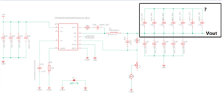
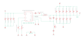
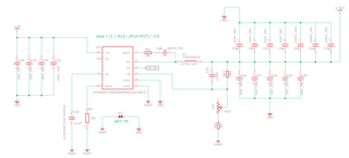
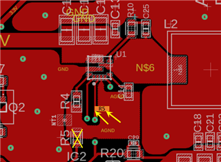
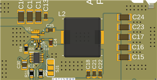
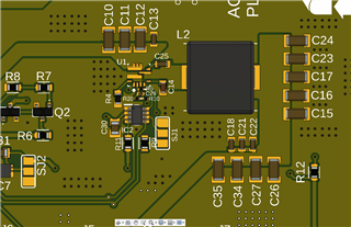
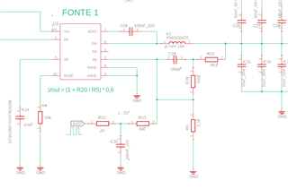
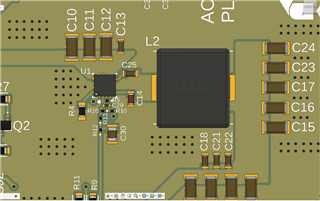
Good afternoon, I made a circuit using the CI texas TPS56837H for testing and evaluation, but I couldn't get the IC to work properly as expected. when feeding the IC with a low voltage (6 to 10 V) the output is activated and regulated, but with a higher voltage it stops working and burns, does not short circuit, but ends up stopping and no longer returning to "life".  I put a potentiometer in the circuit to be able to adjust the output voltage but I don't know if this is possible with the circuit in operation.   I need help as I have already damaged 3 CI's. I'll leave the schematic of the circuit. Thanks in advance for the help and I'm sorry for my English which is not very good.
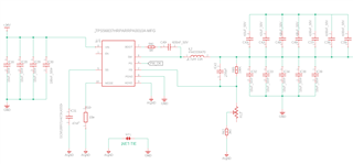
  • Hi Mauricio

    Good afternoon. 

    Why are  C41,C42....C35 used and what are they connected to ?

    " I put a potentiometer in the circuit to be able to adjust the output voltage but I don't know if this is possible with the circuit in operation. "----This should be ok, and should not be the cause for this issue.

    Do you mean when Vin goes higher than 6~10V, the circuit will damage? 

    Thanks and best regards.

  • Good morning GUI HE, these capacitors are connected to GND as shown in the new attached photo. The problem that is occurring is that when I increase the Vin voltage above 10 volts, the IC TPS56837H stops working, as if it were turning off, but it no longer works, I believe I have damaged 3 ICs by carrying out tests. I can't tell if it's a problem with pin 1 enable or if it's my feedback circuit. The tests carried out were without load at the output. Once again, thank you very much for your attention and help.

  • Hi Maurício

    The schematic looks ok.  Did it damage just after powering up? How did you do the test? Did you use a DC source? And did you set the Vin 10V then power up or you power up as Vin=6V then increase the Vin? 

    Can you test the Vin , SW, vo waveform? You can measure the waveform when it operates normally. It will be better if you can catch the waveform when it got damaged, you can use the 'trigger' function of oscilloscope. Triggering the up-slew-rate of the vo. 

    Thanks and best regards.

  • I started the tests with 6 volts (circuit powered by a DC bench supply adjustable from 0 to 30V). with 6 volts the circuit turned on, in the feed back circuit my potentiometer was adjusted to 5K ohm, output signal with +- 6Volts, so I increased the input and output voltage, when I went from +- 8.6 Volts of Vin to Vout remained regulated at 8.6 volts, I raised Vin to 10 volts, Vout remained at 8.6 Volts, the voltage on pin 2 FB was maintained at 0.6 volts. Everything seemed normal and as expected. When changing the VIN voltage to 11 volts the TPS56837H stopped, I tried to return the voltage to lower levels but it no longer responds. with TPS56837H now connected, it no longer shows a switching signal at the output, on its pin 1 EN I measure +-3 Volts, I have already tried to force enable to gnd and then leave it floating but without success, I believe that the Cis are damaged. Tests carried out without load in Vout. I will acquire new Cis TPS56837H to redo the tests and make the oscilloscope captures to send you. Thank you very much for your attention.

  • 245 / 5.000
    I tested the Ci again, feeding it with 12Vdc, I took these screenshots of the Ci:
    Blue line is pin 7 - boot, yellow line is pin 6 SW, pink line is Vout:
     
    Yellow line is pin 6 SW with EN at gnd:
     
    Yellow line is pin 6 SW with EN in floating:
  • Hi Maurício

    The device seems already have issue and there are few information from the waveform. Can you:

    (1) Measure the SW waveform during the normal operation

    (2) Catch the waveform when the damage just happens : you can add the probe of Vin,Vo,SW, and use oscilloscope trigger function, trigger the vo down; (then when you rise vin and the device damage, vo will go down).

    Thanks and best regards.

  • ok, I already bought new Ci's from digikey, as soon as they arrive (10 to 15 days as I'm in Brazil) I will carry out the requested tests and send them here. Thank you very much for your attention.

  • Hi

    Please let me check and get back later,thanks.

  • Hello again. The new texas ci's have arrived, below is the screenshot on the oscilloscope.

    Yellow = Vin.

    Pink = FB.

    Blue = Vout.

    Cyan = SW.

    Here we are with an 8.9V VIN

    Here we are with a vin of 9.3V, see that the Ci has stopped working

    This is the schematic used:


    Thank you very much for your attention.
  • Hi Maurício

    The waveform is abnormal although there is output. The FB voltage should be a stable DC voltage (0.6V).  Also, did the vin oscillation caused by the buck switching ?

    Can you please share the layout image? Did you place the R14 AND the 10k resistor close to the IC FB pin and GND pin? And the FB trace should be avoided from the SW node. 

    C54 should be placed close the the IC VIN and GND pin.

    Thank you!

  • Good morning Gui HE, Yes, the Vin oscillation always occurs after turning on the TPS56837H, my FB circuit is not so close to the IC, below are images of how I made the test board and the complete schematic.
    schematic_test_board.pdf


  • Hi Maurício

    Thanks for your feedback! Bella will get back to you during these days.

    BRs

    Lucia

  • Hi Maurício

    The Feedback resistors are really far away from the FB and GND pin. That might bring some risk.

    Can you manage to place a resistor close to the FB pin? will need to cut some insulation paint on the surface and expose the copper layer.  This might help identifying whether this is the root cause without changing the layout.

    Thanks and best regards.

  • Good morning, I'm going to do this test and let you know how it goes. Below is a new layout review, with the closest components. I would like to know what you think of this new version? Is this better? Once again, thank you very much for your attention and quick response.

    1321.schematic_test_board.pdf

  • Thanks for your feedback. We will check and get back to you by end of next week.

    BRs

    Lucia

  • Hi Maurício

    Looking for your feedback about the test. 

    Also, attach the publications about methods to generate adjustable output for your reference:Dynamically Adjustable Output Using TPS63000,

    The Figure 5 in  Methods of output-voltage adjustment for DC/DC converters can help achieve adjustable output while keep RFB close to FB and GND pins.

    Thanks and best regards.

  • Good morning GUI ELE, thank you very much for your attention. I'm sending the changes so you can review them.


  • Hi Maurício

    Looks ok to me. Also, have you got any test results about the original board? 

    Thanks and best regards.

  • Good Morning Gui ELE, so I ended up not testing the old board because I was afraid of damaging another component, but today I will carry out the test and let you know the results here. Once again, thank you very much for your attention and help.
  • Hi Maurício

    I ended up not testing the old board because I was afraid of damaging another component,--Understand, It's ok.  

    I just wanted to save your time/cost effort of changing layout building a new pcb to identify root cause.

    Thanks and best regards.

  • Hello again Gui ELE, I redid the tests with the old board as per your recommendation, in fact I even added the new output voltage adjustment system according to the schematic sent in previous messages, and now the IC TPS56837H works perfectly, with good adjustment and at full load. Once again, thank you very much for your attention and support.
  • Hi Maurício

    That's great, I will close this thread now, Thank you!

    BR.