This thread has been locked.

If you have a related question, please click the "Ask a related question" button in the top right corner. The newly created question will be automatically linked to this question.

LM61460-Q1: Specifications for Loop Stability Test Parameter Setting

Part Number: LM61460-Q1

Hi,

I am currently conducting a loop stability test for a BUCK converter, mainly testing the Bode diagram. I am confused about the settings and criteria for judging loop stability on the oscilloscope, so I would like to seek your advice.

My output voltage is 5V, input voltage is 9-16V, and the working current is around 5A.

Here are my questions:

1. What is the appropriate range for the starting and cutoff frequencies in the Bode diagram test? My switching frequency is set to approximately 1938KHZ.
2. What is the appropriate amplitude for the alternating signal injected into the loop? I set it to 50mV.
3. What is the appropriate value for the loop injection resistor? I used 50 ohms.
4. What are the reasonable criteria for determining the crossing frequency, gain margin, and phase margin? Can you provide specific criteria? Is this standard applicable to other BUCK ICs as well? I understand that the crossing frequency is generally set to 5-20% of the switching frequency, the absolute value of the gain margin is greater than 12dB, and the phase margin is greater than 45°.

Please help me with this, I really appreciate it!

  • Hello,

    When you say oscilloscope in the context of loop response and bode plot, I'm assuming you are referring to a frequency response analyzer (FRA) like an AP Instruments M200 or a Bode100 instrument correct?

    1. What is the appropriate range for the starting and cutoff frequencies in the Bode diagram test? My switching frequency is set to approximately 1938KHZ.

    You will be able to get all the necessary loop response if you run a sweep between 100Hz to 1MHz as the crossover frequency is usually around 1/10th to 1/5th the switching frequency. 

    2. What is the appropriate amplitude for the alternating signal injected into the loop? I set it to 50mV.

    To get a clean waveform, I would suggest having a variable loop gain injection signal to have a clean low frequency gain measurement. Near the predicted crossover frequency (1/10th of 1938kHz = 190kHz) I would have 30mV-50mV injection so as to not disturb and overdrive the circuit. 

    Ridley has a great article talking about variable loop gain injection signal (https://ridleyengineering.com/design-center-ridley-engineering/41-frequency-response/108-027-frequency-response-measurement-part-5-injection-signal-size.html) that I suggest you reference.

    3. What is the appropriate value for the loop injection resistor? I used 50 ohms.

    This will work. Break the top feedback loop and place this injection resistor between top resistor and Vout rail.

    4. What are the reasonable criteria for determining the crossing frequency, gain margin, and phase margin? Can you provide specific criteria? Is this standard applicable to other BUCK ICs as well? I understand that the crossing frequency is generally set to 5-20% of the switching frequency, the absolute value of the gain margin is greater than 12dB, and the phase margin is greater than 45°.

    As mentioned earlier, the standard for crossover is /10th to 1/5th the switching frequency. Also other rules of thumb are (PM > 45deg) and (GM > 10dB).

    Regards,

    Jimmy

  • Hi,

    Thank you for your answer.

    As for the first point, I would like to consult you in detail. Assuming that my switching frequency is not 1938KHZ, how do I know when to set the range of start and cut-off frequency to get a complete loop response,What kind of data is needed to determine that.

    Regards

  • hello Xiaoye,

    Sorry for the delay, the responsible engineer will provide an update within 24 hours.

    Thanks.

    David.

  • Hello,

    The first point is a general rule of thumb for the crossover frequency of the loop response and scales with frequency.

    So ballpark 1/10th to 1/5th the switching frequency should be the crossover frequency.

    Say you have a 400kHz application, the general rule of thumb stability design would suggest that crossover frequency be around 20kHz to 40kHz. 

    Regards,

    Jimmy

  • Hi,

    Thank you for your reply.

    I have understood your answer, but what I really want to ask is how much is the appropriate range of the spectrum of the Bode chart, and what is the starting point and ending point of the frequency of the horizontal axis of the Bode Chart, and what parameters should be used to determine this

    Regards,

  • Hello,

    Please see technical article (https://www.ti.com/document-viewer/lit/html/SSZTC80). 

    What we use is the AP instruments (M300 software).

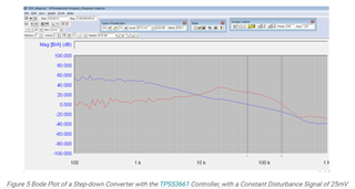
    Starting point is 100Hz and ending point is 1MHz.

    Below is an example of a loop response that is used in the technical article which shows the settings.

    Regards,

    Jimmy