This thread has been locked.

If you have a related question, please click the "Ask a related question" button in the top right corner. The newly created question will be automatically linked to this question.

UCC27301A-Q1: Gate driver design circuit

Part Number: UCC27301A-Q1

Tool/software:

Hello team TI,

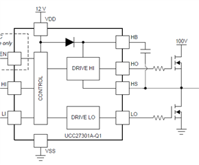
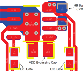
I am using UCC27301A-Q1 gate driver in my motor control application for mosfet driven inverter. I have doubt regarding the bootstrap capacitor for driving the high side mosfet. I have used 0.1 uF 100V ceramic capacitor as per your datasheet but high side mosfet is not turning on and off properly. As a technical test case scenario I placed electrolytic capacitor for bootstrap circuit and also tried different values for bootstraping (4.7uF and 10uF) electrolytic capacitor and performance has shown a better change. Please guide us on which capacitor to take ceramic or electrolytic? And guide us through the bootstrap circuit.


  • Hi Dhruv,

    Thanks for reaching out to TI.

    Ceramic capacitors are very low ESR, whereas electrolytic capacitors are usually higher ESR than ceramic. Electrolytic capacitors also struggle with higher frequency switching and slower frequency response. Thus, we do recommend a X7R ceramic surface mount capacitor with a range of 220nF to 1uF with the UCC27301A-Q1. 

    If you would like to calculate the size of capacitor your system would specifically need, we have this E2E thread calculator.

    This application note, section 2 explains the charge and discharge path of the bootstrap circuit, specifically figures 1 and 2. 

    Thanks,

    Jeremiah