Tool/software:
Hi Team,
We are facing voltage stablity issue with PIN Stap compensation value.
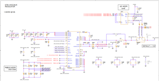
I have attached the excel sheet here for you review it seems everything fine in excel sheet .
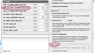
we used PIN Programmed compensation code HEX value (1380421C84) in TI fusion GUI..
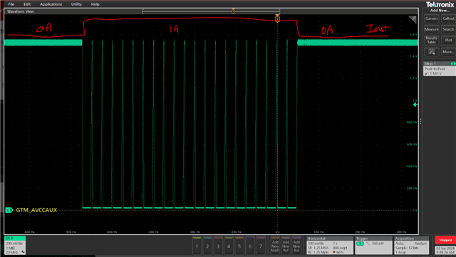
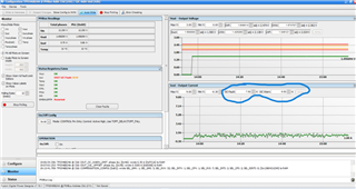
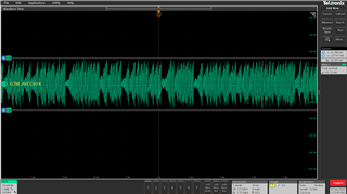
We have seen unstable VOUT with No Load and TRANSIENT condition .I have attached screenshot of GUI and MSO
NL-
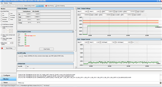
TRANSIENT (0-5A)
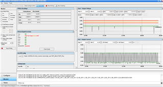
I have changed the transient 0-1A for below snap
TRANSIENT(0-1A) from MSO
![]()
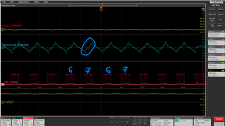
RIPPLE-
So based on excel sheet calculation (TPS546x24A_Compensation_Pinstrap_Calculator) how we should assure that the design will work fine.Please highlight if we missed anything in the excel sheet.