This thread has been locked.

If you have a related question, please click the "Ask a related question" button in the top right corner. The newly created question will be automatically linked to this question.

LMG2100EVM-078: LMG2100R044

Part Number: LMG2100EVM-078

Tool/software:

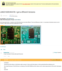
The question of different versions of this EVM wasn't fully answered (see original question below - thread is locked).  I have an EVM (just received) that has the inductor on top.  The revision marking on the board silkscreen is Rev A (which doesn't agree with the answer given in the previous thread).  I also noticed the schematic does not match the board.  The schematic shows C7, C12, and C16 as part of the output capacitor bank.  However those capacitors are not on the board, nor are there any footprints for them.  That makes me question the values of capacitors that are present on the PCB.  Can TI provide accurate documentation for the EVM version that has the inductor on top?

  • Hi Paul,

    I have attached here the schematic for the board you have. This is the updated version, but they still say RevA on the silkscreen. C7 & C12 were removed from the design. C16 should still be there right next to C19, the silkscreen label for C16 may be covered by a screw hole.

    LMG2100EVM-078_SCH.PDF

    Best,

    Kyle

  • Thanks for sending the schematic.  I noticed there is an error on the schematic.  It shows that both R11 and R13 are installed as 0 ohms.  That obviously would not work.  The EVM board as delivered does not have R13 installed.  Best to update your schematic to prevent confusion for others and also add the schematic on the TI EVM webpage.

  • Hi Paul,

    You are correct, if R13 is populated then R11 should not be populated (single PWM input mode). If R11 is populated then R12 & R13 should not be populated (split PWM input mode). This note can be added to schematic for clarity.

    Best,

    Kyle