This thread has been locked.

If you have a related question, please click the "Ask a related question" button in the top right corner. The newly created question will be automatically linked to this question.

TPS552882: Average inductor current limit not working

Part Number: TPS552882
Other Parts Discussed in Thread: TPS552872

Tool/software:

Hi everyone, 

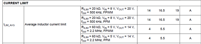
I think the average inductor current limit is not working properly in this device. I have a 20V/1.5A output, but I wanted to limit the average inductor current (=output current) to ~2A. I tested both Rilim = 180k (1.84A limit) and 200k (1.65A limit) and the controller is not shutting down and it's still running even at 2A. As far as I read in the datasheet, the formula is really straight-forward: Rilim = 330000/ilim, so could anyone let me know why is this nor working properly? 

Thank you in advance!

Best regards,

Juan

  • Hi Juan, 

    Thank you for reaching out. What is input voltage when you do the test? Can you provide your schematic so that I can see if there is any design problem.

    Regards,

    Mulin

  • Hi Mulin,

    Thank you as well for the quick answer. The input voltage is 25.2V and the output voltage is 20V. The rest of the system is working fine (both the power stage and the control loop), but the only thing which is not working fine is this protection. Would you have any idea what's happening? Unfortunately, I cannot share the schematic, but everything else is working fine as I just said. 

    Best regards,

    Juan

  • Hi Juan,

    Can you help provide the sw1, sw2, vout,  inductor current waveforms to me ?

    You can share the screenshot of only TPS552882 external component to me. If not convenient here, my e-mail address: mulin-yuan@ti,com.

    Regards,

    Mulin

  • Hi Mulin, 

    I sent you the screenshot of the TPS552882 design to your email. Regarding the waveforms, I measured everything (except for the inductor current) at maximum current (1.5A), and the screenshots are shown below: 

    SW1:                                                                                              SW2: 


    Vout @25.2Vin:                                                                              Vout @15Vin: 


    Best regards,

    Juan

  • Hi Juan,

    About schematic, recommend to add a 0402 0.1uF capacitor and put them as closely as to the device.

    I check with team that TPS552882 can not support that low current limit. Please refer to the datasheet. The minimum value is about 2.6A. So can you accept to set the limit around 2.6A?

    By the way, with your power, TPS552882 has too much margin. Recommend to use TPS552872, which is four MOSFET integrated. Fixed inductor current limit is 4A.

    Regards,

    Mulin

  • Hi Mulin, 

    The 100nF capacitor of course is placed closed to the VIN pin of the device. And I checked the datasheet beforehand but the minimum average current setting is not clarified in it (and changing the DC/DC is not an option anymore). This is not a problem because all other features of the converter are working fine.

    Just to learn how TI datasheets work a bit more in depth: if the curve only shows resistances up to 100kOhm, can't it be interpolated for higher resistor values? I mean, does that imply that the maximum resistance that can be connected to ILIM is 100kOhm? Is that a generic feature (curves in the datasheets can't be interpolated) in all TI datasheets? 

    Thank you again for your time!

    Best regards,

    Juan

  • Hello Juan,

    Please expect an answer to your questions tomorrow as the expert to this device is out of the office today.

    Best regards,
    Brigitte

  • Hi Juan,

    Thank you for your question. About TI datasheet generic feature, I think it is case by case. When the datasheet points out application range, it is guaranteed. If  not, it is sure that what is shown in datasheet table or figure is guaranteed. And what is not shown needs to be verified with experiment or simulation from my understanding. So I recommend you to set the limit inside datasheet range.

    There is another factor may have influence. As we know, there are variation between different single device. Below table shows that with same RLIM, inductor current limit may vary(2.5A difference maximum). So when you limit to 1.5A, there is possibility that result differs. 

    I hope my answer can help. If you have other question or opinion, feel free to tell me.

    Regards,

    Mulin