Other Parts Discussed in Thread: UCC256302,
Tool/software:
Hello,
we are currently migrating from UCC256302 to UCC256602 due to NRND of UCC256302.
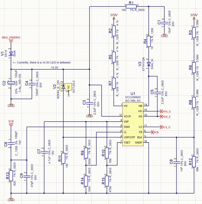
We have trouble with the bootstrap circuit, our high-side driver keeps dying. In the UCC256302 this same power stage and bootstrap circuit worked flawlessly.
The High-Side driver typically dies within the first switching cycle. MOSFETs do not get damaged, only the high side driver is destroyed. The resistance between HB and HS always drops to exactly 700 Ohms, I tried this multiple times. After replacing only the dead UCC25660, the circuit works again. So only UCC25660 is damaged, nothing else in the circuit.
The damage only occurs when operated at our target voltage (370V). When using only 200V, it works perfectly.
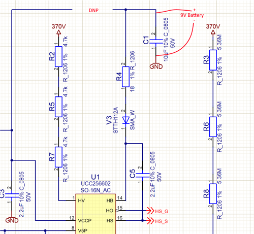
I am sure it has to do with the bootstrap circuit, because disconnecting the bootstrap diode and supplying the high-side driver with a 9V battery is successful. As stated, this bootstrap circuit worked with UCC256302.
The damage occurs in the first switching cycle. First, the LS FET switches on, charging the bootstrap capacitor. Then, the HS switches on, the switching edge is not very steep and no overshoot occurs. After 100ns, the HS driver dies, we can see this as the voltage in the bootstrap capacitor rapidly starts to drop after 100ns and the resistance of the high side switch increases, leading to a voltage drop in the switching node / falling edge:
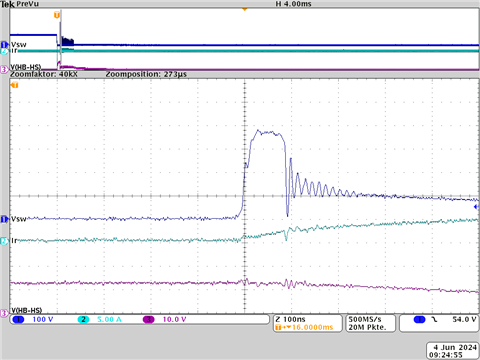
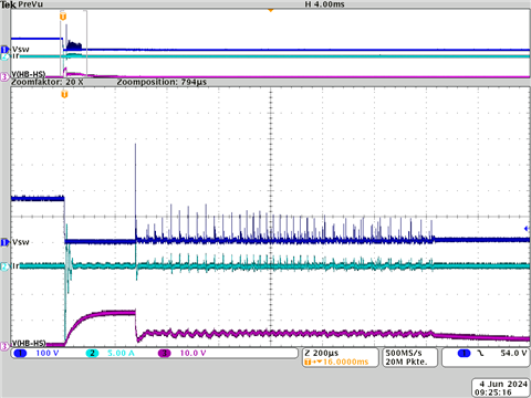
CH1/Blue: Switching Node
CH2/Green: Resonant current
CH3/Violet: HS Driver Voltage
As a comparison, this is how it should look (using a 9V battery for the high side driver instead of the bootstrap circuit):
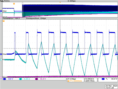
CH1/Blue: Switching Node
CH2/Green: Resonant current
CH3/Violet: Output voltage (divers from above)
The first switching cycle is normally (with 9V battery) ca. 600ns long, but our driver fails after 100ns (with bootstrap). Thus, it is very likely that first the driver dies and then the falling edge begins. From the oscilloscope pictures, I cannot see any overvoltage / undervoltage events on the HS driver. Over and undershoot is not visible before the driver dies.
Our bootstrap capacitor is 2.2uF, our diode is STTH112A (ultrafast diode 1200V 1A). We started with 2.2 Ohm for the bootstrap resistance (as in our old circuit), and already increased it to 18 Ohms. In addition, I tried adding a 18V Z-Diode to limit overvoltage peaks directly between HB and HS. Also, I removed the diode from the bias winding to VCCP to ensure that no overvoltage on the VCCP-pin occurs (supply only from HV). I increased the MOSFET gate resistors from a very low value to a very large value to reduce switching edges (now ca. 10V/ns).
=> So far, all of these measures themselves and all at once did not lead to a success. Only operation with 200V instead 390V or operation with a 9V battery instead of the bootstrap circuit works.
Do you have any ideas what to try next?
Otherwise, how is it actually possible to damage the HS driver without damaging the MOSFET? Are there any ways other than over/undervoltage and too steep switching edges?
Thanks for your help.