This thread has been locked.

If you have a related question, please click the "Ask a related question" button in the top right corner. The newly created question will be automatically linked to this question.

LM5180-Q1: Verify the calculation of operation mode and power consumption

Part Number: LM5180-Q1
Other Parts Discussed in Thread: LM5180, LM5181

Tool/software:

I start to do worst case analysis for our design and I have some confusion about the LM5180 PSR flyback converter quickstart tool  and datasheet.

Datasheet- https://www.ti.com/product/zh-tw/LM25180-Q1

The attachment is quickstart tool from TI. https://www.ti.com/tool/LM5180DESIGN-CALC

According to the datasheet of equation, I can calculate the maximum output current (follow the figure)  in different input voltage.

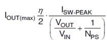
The ratio of output power is relative to the output power and maximum power that will affect the operation mode of LM5180

 Please help us provide the equation of total rate power(figure 20 in datasheet)

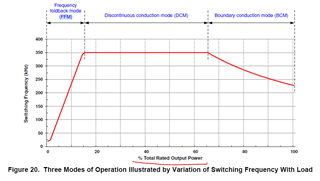
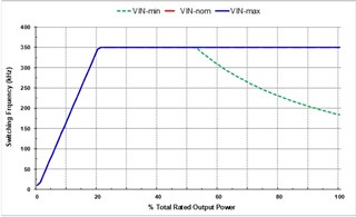
According to the quick calculation tool, the operation mode is different curve in different input voltage (follow the attachment)

Could you help me to verified which one is correct(and how to calculate these curve)?

How to calculate the power consumption of IC because delta need to analysis the maximum junction temperature?

Asker Cheng 

  • Hi Asker,

    Thank you for posting. Since I am currently on the road of the business trip, I will answer your questions in more detail next week.  Here let me give you some brief answers and see if it helps.

    1. the datasheet figure of Fsw vs Load in percentage is an just an arbitrary example to illustrate the three operating modes:  FFM, DCM and BCM, in the order of increasing the power. The positions of the turning point between two modes can move right or left depending on specific designs.  You can see that when you change the inductance in the design calculator, the frequency curve varies.  Next week I will share the equation of total power, but you may be able to work these out by noticing the following:

    1.1  In FFM, the peak current is constant at 20% of the SW max peak current limit. For LM5181, it is 0.15A Typical.  The frequency will vary.

    1.2. In DCM, the frequency is constant at 350kHz, and the peak current varies with load.

    1.3. In BCM, the duty cycle is constant.

    Since the circuit only operates FFM, DCM or BCM, the total power is always determined by:  1/2 x Ipk^2 x Lmag x Fsw.

    2. The IC power consumptions include the IC controller section power consumption including the internal VDD LDO's, and the power MOSFET losses including both the switching and conduction losses.  Please wait until after I return to office next week. 

    Thanks,

    Youhao