This thread has been locked.

If you have a related question, please click the "Ask a related question" button in the top right corner. The newly created question will be automatically linked to this question.

UCC2818-EP: Power management forum

Part Number: UCC2818-EP
Other Parts Discussed in Thread: UCC2818, UC2854

Tool/software:

Hi TI team,

I have following requirements

  • Input voltage -100Vrms to 134Vrms
  • Frequency- 360Hz to 800Hz
  • output voltage- 400V
  • output power 100W

I am planning to UCC2818-EP PFC IC.

Do i have to change any parameters in the IC pin except Vff filter capacitor to work properly at 400Hz.

Please advice.

  • Hello,

    Is there any reason why you prefer -EP version? Is it for Avionic?

    Thanks,

    Ning

  • Hi Ning

    Yes it is for Avionics application

    Regards

    Rahamadullah

  • Hello Rahamadullah, 

    To use the UCC2818-EP controller at 400Hz (or higher) the design work is similar to that for 50Hz applications, except that items involving the line frequency are scaled to the higher frequency.  These items include Vff filtering and voltage-loop and current-loop cross-over selection and compensation.

    In addition, just today I found this reference to a paper from Virginia Tech on improving THDi in Avionics: /cfs-file/__key/communityserver-discussions-components-files/196/7028.5_5F00_10841.pdf 
    You may find this useful. 

    Regards,
    Ulrich

  • Thanks Ulrich,

    This helps us a lot.

    Have one more query on this IC. When i looking into datasheet design for Vff pin, the second harmonic magnitude is mentioned as 66.67% of average value. I think it is (1/15) th times of average value which 6.67%.

    Is this a typo error or it is my misconception?

    Please clarify

    Regards

    Rahamadullah

  • Hello Rahamadullah, 

    I'm glad that paper can be of help. 

    Concerning the 66% second harmonic magnitude, that is not a typographical error. 
    The datasheet procedure is calculating how much attenuation is needed to reduce a signal amplitude from 66% of the line voltage to 1.5% of the line voltage.
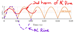
    That signal is the fundamental frequency amplitude of the rectified line which is 100Hz, and 100Hz is the 2nd harmonic of 50Hz.  (Or, 120Hz from 60Hz.)
    The point is to minimize (as much as practicable) the 100Hz ripple on the Vff signal that feeds into the multiplier whose output carries some component of that ripple into the current -loop and contributes to THDi.

    Here is a paper that includes an in-depth discussion of sources of and reductions for THDi.  It was written to support use of the UC2854 controller, but much of it is applicable to the UCC2818 (and similar devices) as well.  See the first few pages of this paper: 
    slup093.pdf

    Regards,
    Ulrich

  • Hi Ulrich 

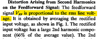
    In Pg.No 4 of the file slup093.pdf  you have shared says second harmonic magnitude is 66.6% of average value attached snip below.

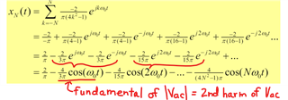
    The full wave rectified sine wave 2nd harmonic is actually 6.67% instead of 66.67% as per the fourier series equation

    If we put K=2 (harmonic number) in above equation we get the ratio of 2nd harmonic to the avg value is 6.67% or (1/15).

    Also in Pg.No 10 of UCC2818-EP datasheet it is mentioned as " The second harmonic is 66.67% of ac line input voltage" instead of average value of rectified input voltage.

    So if this is the case then i have to consider 6.67% as the distortion level by second harmonic to calculate Vff capacitor value. Please clarify

    Regards

    Rahamadullah

  • Hello Rahamadullah, 

    First of all, the file SLUP093 and the datasheet say "66%", not 66.6% or 66.67%.   I point this out for a reason to become clear below. 

    Second, from the harmonics file that you found (https://sceweb.sce.uhcl.edu/harman/CENG3315_DSP_Spring2020/00_3315_2021/3315_web_2021/3_Ch3_FWRS_MATLABPresentation1.pdf) on page 8, it shows the equation of harmonics which construct the rectified AC sine wave: 

    Please note that SLUP093 and the datasheet refer to the 2nd harmonic of the AC line, not of the rectified line. 
    The fundamental of the rectified line is the 2nd harmonic of the AC line.

    Its peak amplitude is 4/3pi = 0.4244 of the rectified sine peak.  This is neither 0.66, nor 0.06, so I can only guess where 0.66 (66%) comes from.

    My guess is this: 
    Peak of fundamental component (100Hz) of rectified 50Hz-sine = 0.4244 of peak of rectified 50Hz-sine.
    SLUP093 refers to the RMS line voltage:

    Since the peak of the line = 1.4142 x Vrms, I think that 2nd harmonic amplitude = 0.4244 x 1.4142 = 0.600 of Vrms, and 66% = 0.66 = a typo of 0.60.
    That is, I think the author of SLUP093 inserted a typo of 66% instead of 60% (of Vrms rather than Vpeak) and continued that mistake through the rest of the calculations. 
    I don't have any better ideas on where "66%" comes from, and the author is not available to ask.

    In any case, the calculations are conservative (reducing the 2nd harmonic more than necessary) so no harm is done other than possibly over-designing the Vff filter.  I believe that the calculation method is still valid, even if one of the factors was incorrect.

    Regards,
    Ulrich