UCC27282-Q1: UCC27282QDRQ1 IC Getting Damaged

Part Number: UCC27282-Q1

Tool/software:

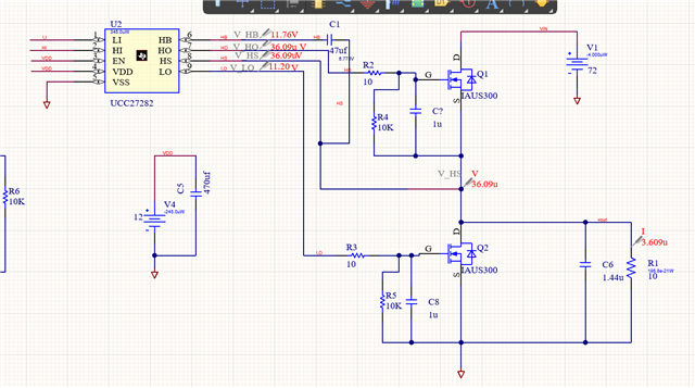
We are using UCC27282QDRQ1. We want to run motor at 72V & 250A current. we are not able to run IC above 48V. Above 48V IC & MOSFET are getting Damaged. I have attached the circuit we are using. Please verify & suggest solution.

  • Hey,

    Thank you for reaching out to TI with your question regarding the UCC27282-Q1.

    Looking at your schematic, there may be some changes that can be made to optimize the circuit. Please take a look at the following questions and suggestions:

    1. The bootstrap capacitor (C1) and VDD capacitor (C5) sizing and location on your PCB. They should be located as close to the gate driver as possible, be X7R ceramic and be sized according the the calculations outlined in Section 8.2.2.1 Select Bootstrap and VDD Capacitor.

    2. The capacitors in parallel with Vgs of the FETs (C7 and C8) are adding load to the gate driver and will slow down your rise and fall times. Is that okay?

    3. What is their operating frequency and maximum duty cycle? What is the operating condition they are seeing this at? Is it steady state or startup for instance?

    4. With the high load and input voltages that you are seeing, you are likely to be seeing overshoot beyond the absolute maximum ratings of the gate driver. Please measure HB-VSS, HS-VSS and HO-HS at the pins of the gate driver during this operating condition to ensure that this is not being violated.

    Let me know if you have any questions.

    Thank you,

    William Moore

  • 1) we have calculated the capacitor value & assembled the same on board but we have reference schematic of another board on that they have used capacitor value in uF but calculated value is in nF.

    2) these capacitors are used for simulation purpose only not on board.

  • Hey Ankita,

    That would be correct that nF is a more likely scale for these capacitors.

    Can you please share your insights on questions 3 and 4 above?

    Also, to better understand what is being damaged, can they take impedance measurements from each pin with respect to VSS as well as from VDD-HB of a known good unit and a known damaged unit? This should be done with the IC off of the PCB and on the bench.

    Thank you,

    William Moore

  • Hey Ankita,

    Have you been able to resolve this issue? If so, can you share your findings?

    If not, can you please provide an update on the status of it and responses to my able questions?

    Thank you,

    William Moore

  • Hey Ankita,

    I am going to close this thread at this time. If you have further questions or updates regarding this issue, please feel free to reopen and update this thread.

    Thank you,

    William Moore