LM61460-Q1: RBOOT sw node rise time

Part Number: LM61460-Q1

Tool/software:

Hi team

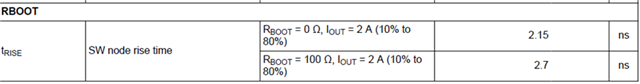
Can you please offer the below spec for LM61460-Q1?

1. More data with different RBOOT value, for example, 470ohm, 1kohm?

2. considering part to part variation, please also give the max and min value for this spec.

3. what's the acceptable range of RBOOT if efficiency is not considered?

thanks!

  • Thanks Terry ask the question for me.  What's more, we want to check, why there is ripple during the rising of switching signal (refer to waveform below) when we change Rboot to higher values (like 470ohm)?  

    Thanks

  • Hello,

    In the datasheet we do not recommend RBOOT values beyond 100ohm. See Section 10.2.2.7. Since we do not specify anything beyond 100ohms. I recommend testing with 100ohm or 0-ohm RBOOT to see if it resolves the issue. What is the specific reason for such large values of RBOOT?

    Best regards,

    Ridge

  • Hello Ridge, 

    Thanks for your reply. We change the Rboot to high value in order to solve EMC emission overtaking issue at RKE band (433MHz). We found that increase the Rboot value can improve the EMC emission. 

    Thanks

  • Hello Ridge,

    Could you please help to confirm if 470R for Rboot is acceptable or not?  We checked that it improves the EMC emission result, and we checked the power supply electrical characteristics (like output voltage accuracy, output ripple voltage, transient response, power efficiency) are almost the same between Rboot=100R and Rboot=470R.. The only difference is that the rise time of switching signal increases and the IC has more temperature rise when Rboot=470R (but it is within spec).  From the measurement, it seems no issue to change Rboot to 470R.  But anyway, we need confirm with TI.  Thanks.

  • Hello,

    Since we do not offer specific recommendations beyond 100ohm in the datasheet, I cannot offer confirmation on specific changes in performance when Rboot is increased to 470ohms across devices. Increased Rboot will increase the SW rise time and will cause a further decrease in efficiency, which may be why the device heats up more. It is up to you, the end customer, to make sure that your design is stable and operates within your design requirements. 

    I recommend using the Rboot values mentioned in the datasheet along with spread spectrum to help solve this EMC issue.

    Best regards,

    Ridge

  • Hello Ridge,

    Got your point and then we would like to confirm if changing the Rboot will only affect the SW rise time and the power efficiency?  Because the rise time and power efficiency we can check it by measurements. Is there any other concerns would happen? like will it lead to the internal HS Mosfet is not turn on/off properly?  In the datasheet we find below simplified circuit of the Mosfet driver, but it is not clearly to understand how it works. Could you please provide more detailed driver circuit inside IC, to help us understand the risk with higher Rboot value. 

    Thank you!

  • Hello,

    The values recommended in the datasheet will provide a safe design. We recommend staying within the datasheet recommended range of values.

    Best regards,

    Ridge