This thread has been locked.

If you have a related question, please click the "Ask a related question" button in the top right corner. The newly created question will be automatically linked to this question.

UCC28070-Q1: Three-Phase Semi-Bridgeless PFC Topology

Part Number: UCC28070-Q1
Other Parts Discussed in Thread: AMC1302, UCC28070, UCC3818A, UCC28060

Tool/software:

Hi

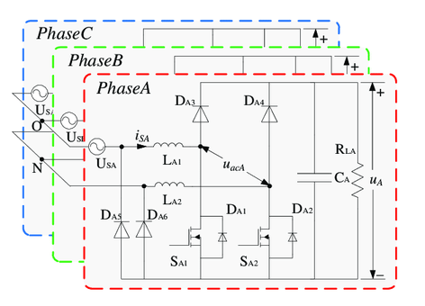
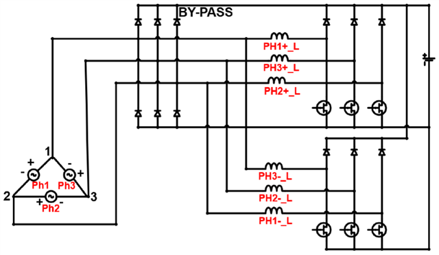
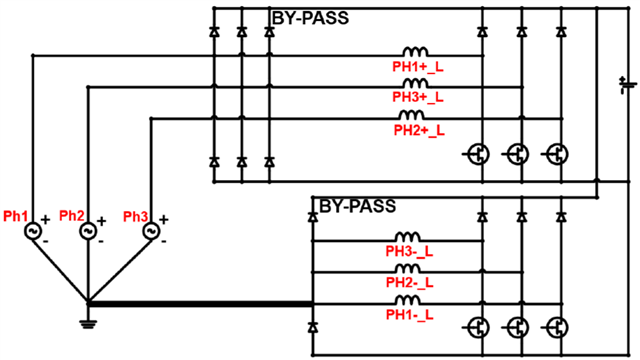
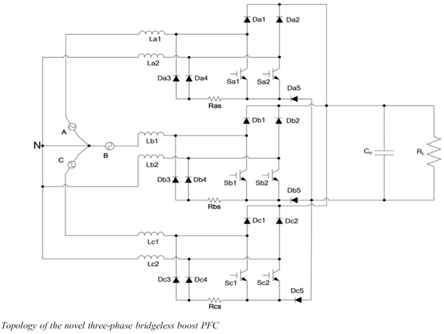
I'd try the Three-Phase Semi-Bridgeless PFC Topology Using UCC28070-Q1 (Analog IC).

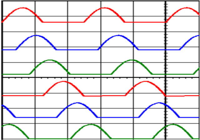
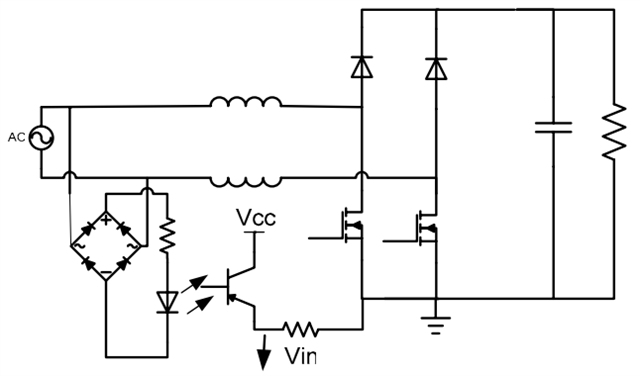
The principle is using the isolatedhalf sine wave reficier and using the Isolated Amplifier(AMC1302).

Biasing the isolated sine wave to the Pin.5 (VINAC) of UCC28070, and the current sense is isolated by current transfomer.

The Vinac signal and Current signal are both isolated.

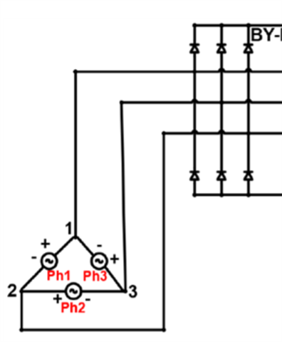
The Three-Phase Semi-Bridgeless PFC Topology incould six low side mosfet, each mosfet work half sine cycle, and each mosfet comtrolled by each UCC28070.

Could the topology work corrently?  

Thanks.

  • Hello Andy, 

    I understand what you are hoping to accomplish with these topology variations, but it simply is not possible to achieve full 3-phase sine-wave current shaping with a single PFC output with these topologies, whether using UCC28070 or UCC3818A (as in a previous E2E: https://e2e.ti.com/support/power-management-group/power-management/f/power-management-forum/1349504/ucc3818a-dual-ac-input-pfc-parallel ) or any other controller from any other vendor. 

    It is not even possible to achieve partial PFC as in the 6-diode rectification structure where the phase currents resemble tombstones.

    Your first figure, showing Phase A on top of Phase B and Phase C, do not have their respective outputs connected together. 
    If these separate output each go to separate isolating DC-DC-converter, then the DC-DC outputs can be tied together to power a single common load. 
    In this manner, each of the 3 AC phases can have full PFC using 3 separate PFC controllers. 

    But your circuit diagrams with Ph1, Ph2, Ph3 inputs all have a common PFC output GND net, and this cannot work. 
    It looks good on paper, but the phase currents will try to force the PFC_GND to conflicting voltage levels, and these conflicting voltages will short-circuit one of the phases' voltage to a different phase's voltage.  There will be a short-circuit current through the diodes.  At best, a fuse will blow before damage results. 
    At worst, several devices will be damaged before a fuse can clear.     

    Over the years, many engineers much smarter than me have looked for simple ways to interconnect a 3-phase AC input to achieve a single PFC output. 
    So far the "simplest" ways are variations of the Vienna Rectifier.  If circuits as simple as your figures above were possible to work, they would have been standard design practice for a long time already. 

    Regards,
    Ulrich

  • Hi Ulrich Goerke

    I found some paper about using simple ways to interconnect a 3-phase AC input to achieve a single PFC output. 

    Study and design of a novel three-phase bridgeless boost power factor correction

    Open Circuit Fault Diagnosis and Fault Tolerance of Three-Phase Bridgeless Rectifier

    Research on the Nonlinear Control Strategy of Three-Phase Bridgeless Rectifier under Unbalanced Grids

    I do believe Three-Phase Semi-Bridgeless PFC Topology could work well, but the control is a big issue.

    But your circuit diagrams with Ph1, Ph2, Ph3 inputs all have a common PFC output GND net, and this cannot work. 
    It looks good on paper, but the phase currents will try to force the PFC_GND to conflicting voltage levels, and these conflicting voltages will short-circuit one of the phases' voltage to a different phase's voltage.

    If these mosfet do not switch(do not work), will the delta three phase power to the six diodel short-citcuit?

  • Hi

    https://e2e.ti.com/support/power-management-group/power-management/f/power-management-forum/1279328/300w-pfc-with-input-3-phase-delta-3-wire-220vac-l-l-50hz/4852458?tisearch=e2e-sitesearch&keymatch=3%2520phase%2520analog%2520pfc#4852458

    On this page

    TI__Guru 69105 points

    Hello,

    The UCC28060 is interleaved PFC and will work on single or dual phase input with a single rectifier.  As far as 3 phase TI does not offer at 3 phase controller.

    However the C2000 can achieve 3 phase input PFC with a Vienna rectifier.

    You can do 3 phase PFC with analog controllers.  This is generally done with 3 PFC boost pre-regulators one used for each phase.  This will require a bridge rectifier for each phase, each PFC stage will need to be galvanically isolated from each other and will need separate isolated DC to DC conversion; as well as, load sharing.  In the end  you will find that the C2000 is much cheaper.

    3 phase line power is generally used for high power applications 300 W sounds kind of low.   What is this PFC front end trying to control?

    Does UCC28060 work on dual phase??  

    Thanks.

  • hi

    On this paper "IET Power Electronics - 2014 - Chen - Study and design of a novel three‐phase bridgeless boost power factor correction", the topology is three-phase bridgeless boost PFC.

    Each mosfet has its corresponding inductance, on my opinion, that will avoid short circuit.

    Is that right?

    Thanks

  • Hello Andy, 

    Thank you for sharing this paper on novel 3-phase interconnection to a common PFC output.
    Obviously, the paper proves that it works.

    I will have to study this in detail to understand how it works and how the controller can interface with it. 
    My main concern is how a single Vout feedback signal can be sent to 3 different controllers, each at different GND references. 
    I think they probably need isolation amplifiers. 
    The paper does not provide details on how the real-world control is connected.  The simulation control "circuit" is not realistic. 

    I have not yet looked for the other papers that you listed. 

    The UCC28060 works on single-phase only.  The term "dual-phase" is also sometimes referend to as "split-phase" and is simply a single-phase line with a Neutral tap in the center (such as 240Vac phase-phase = +120Vac phase-neutral and -120Vac phase to neutral).  Dual-phase is single-phase as far as the PFC input is concerned, but it is confusing terminology.   

    My conclusion is that if an IR1150 can be made to work with this topology, then the UCC28070 can also be made to work (or any PFC controller with average current-mode control). 
    At this time, I do not know the details of how this can be done. 
    For the UCC28070, I think maybe each phase in the figure above will need to be duplicated into 2 interleaved switching phases for each AC-line phase. 
    In other words, double all the inductors, diodes, and switches (except Dx5).
    Also, I don't think this topology can work with Delta input, only Wye input. 

    Regards,
    Ulrich