This thread has been locked.

If you have a related question, please click the "Ask a related question" button in the top right corner. The newly created question will be automatically linked to this question.

TPS61033-Q1: The issue of Bode diagram

Part Number: TPS61033-Q1

Tool/software:

Hello team,

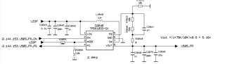
About TPS61033-Q1,we use to boost 3.3V to 5.15V in our system.

The design shown below.

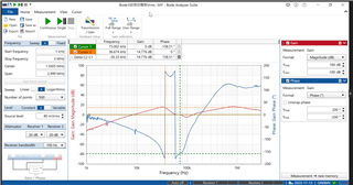
It shows that the Gain and Phase crossover 0 several times no matter 0.5A,1A or 1.5A load.

We have confirmed the setup and instrument  are OK .

I want to know the probable causes.

Thank you!

  • Hi Ailing,

    Thanks for using E2E.

    The bode diagram looks like not the right result.

    Is the R2040 0ohm in your testing? I guess you injecting small signals on this resistor, right?

    If that, it should be several tens of ohms when testing bode diagram, not 0 ohm, we use 50ohm usually.

    Regards,

    Nathan 

  • Is the R2040 0ohm in your testing? I guess you injecting small signals on this resistor, right?

    Hello Nathan,

    Thank you for your quick response, we  did have changed the R2040 to 5ohm and inject small signals on this resistor, and the result  as shown before.

    And there are several DCDC power in our system, we have confirmed the setup is OK.

    If that, it should be several tens of ohms when testing bode diagram, not 0 ohm, we use 50ohm usually.

    Are you sure it's 50ohm rather than 5ohm?  Will it be better if I change R2040 from 5ohm to 50ohm? Anything else I can do to improve it?

    Thank you!

  • Hi Ailing,

    I think maybe the test probe A/B of Bode Analyzer is reversed. Because usually the Gain curve should decrease as frequency increases, but in your results, the Gain curve is increases.

    About the resistor, the output current of Bode Analyzer may be limited if you use too small resistor, you could double check the max current capacity of your Bode Analyzer and have a try.

    Regards,

    Nathan