Other Parts Discussed in Thread: TPS25750, BQ25798, TPS25751
Tool/software:
I want to use the schematic of this evaluation board for my device, which is battery-powered. I plan to use these two chips(BQ25798 and TPS25750) for managing the battery charge and then using the charged battery to supply power to my device.
I have a few questions and would appreciate some clarification:
1. To use battery power for my device, can I use the SYS output?
2. Since the I2C lines of these two chips are connected together, how can I access each chip individually with my µC?
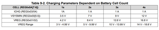
3. My device requires a 24V, 1A power supply, and I use a 3S battery. Is it possible to configure the SYS output to 24V and directly connect my device to this output?
4. When the charger is not connected through USB Type-C, can I use the 5V output?