This thread has been locked.

If you have a related question, please click the "Ask a related question" button in the top right corner. The newly created question will be automatically linked to this question.

MC33063A-Q1: Vout is 8% higher than we expect

Part Number: MC33063A-Q1
Other Parts Discussed in Thread: MC33063A

Tool/software:

Hi.

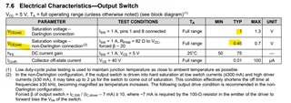
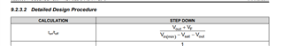
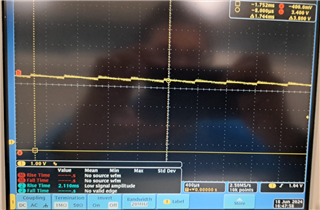
I have a question about the MC33063A converter. We are using R2 = 18K and R1 = 11K, with a desired Vout of 3.3V; however, we are getting 3.59V when Vin is 24V. The capacitance Ct is set to 220pF. Do we need to change the value of Ct? I have been experimenting with different values for CT (300pf, 600pf, 1.1nf) using the PSPICE for TI model, but I cannot achieve a Vout of 3.3V.


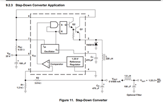
Additionally, Vfb = 1.35V instead of 1.25V

  • We were able to solve the problem by increasing Sense Resistor from 0.33ohms to 1ohms. Could you explain how the sense resistor affects the feedback loop? 

  • Hello Andres,

    Thanks for reaching out to us via e2e.

    First of all: Do you have a physical board or are you only talking about a PSPICE simulation?

    Are the voltages you mention average voltages or peak voltages?
    Do you have oscilloscope screenshots from the real measurements?

    Which load is connected on the output?

    Did you calculate the sense resistor Rsc and the inductor according to that load?
    Simply changing the voltage divider resistor(s) may not be good enough.

    Best regards
    Harry

  • I have a physical board. 
    The voltages are average voltages. 

    The load is only an MCU.

    We designed the converter to source 60mA, but I think we didn't follow Rsc = 0.3/Ipeak. I want to make sure that we selected the inductor properly. We have this formula:

    Lmin = ton_max*(Vin_min - Vsat - Vout)/(Ipeak)

    Where Vin_min = 19V
    Vout = 3.3V
    Ipeak = 2*Iout_max = 120mA
    I am not sure Vsat, is it 1V or 0.45V?


    For Ton_max/(Toff_min) = (Vout + Vf)/(Vin_min-Vsat-Vout)? I calculated Ton_max as Dmax = Vout/Vin_min = 3.3V/19V = 0.173. D = Ton*Fsw => Ton_max = 0.173/(50kHz) = 3.47uS.

    So getting Lmin = 3.47uS*(19V-0.45V-3.3V)/(0.120A) = 440uH? Assuming that Vsat = 0.45
    Vf = Forward voltage drop of the chosen output rectifier=0.4V


    I think the problem is with the inductor and Rcs, as the PSPICE simulation shows issues when L = 100µH, resulting in Vout = 4V. However, when I reduce L to 10µH, Vout drops to 3.33V. On the physical board, I am getting 3.39V by just modifying Rcs.

    I want to verify if we are calculating L correctly.


  • Additionally, how do I check my Switching frequency? Because I am checking Vsw (pin2) and I am getting period of 438uS = 2.3kHz (Ct = 220pF). 

    This is Vout = 3.4V

  • Hello Andres,

    You have connected pin 1 and pin 8, so you are using Darlington mode.
    The "nominal" value for Vsat in Darlington mode is 1V.
    As you can see in figure 3 (the upper curve is for Darlington mode), the saturation voltage depends on the collector current.
    For 120mA peak current it will be around 0.7V

    So, for the minimum inductor value I would calculate around 500µH.


    Your main problem is that the value of the sense resistor is too low.
    0.3 / 0.12 = 2.5
    So, even the 1 Ohm resistor is still too low.
    This means that the transistor inside the controller will turn off much too late (at a much higher peak current.
    And therefore the amount of energy that gets transferred to the output (while the transistor is on) is much too big.
    This energy is stored in the output capacitor.
    If you are using 470µF, this is also much bigger than necessary.

    Do you have a load connected on your real board, while you are doing the measurements?
    It will take a very long time until this energy is getting consumed.
    Only when the output voltage falls below the threshold, the controller is allowed to turn on the transistor again.
    The size of Ct does not make any difference in that case.

    Best regards
    Harry