This thread has been locked.

If you have a related question, please click the "Ask a related question" button in the top right corner. The newly created question will be automatically linked to this question.

TPS38700Q1EVM: Cannot connect USB-TO-GPIO2 to TPS38700Q1EVM (Fusion-Digital-Power-Designer-7.6.6)

Part Number: TPS38700Q1EVM
Other Parts Discussed in Thread: USB-TO-GPIO2, , TPS38700-Q1

Tool/software:

Hey,

I bought the TPS38700Q1EVM and the USB-TO-GPIO2 and downloaded the TI-Fusion-Digital-Power-Designer-7.6.6 version.

This specific version is what TI website offer me to download from the EVB URL, and not the newer Fusion-Digital-Power-Designer (the most updated version is 7.10.1 and doesn't support the TPS38700C).

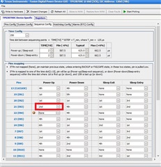
When I open the software I get the following error: 

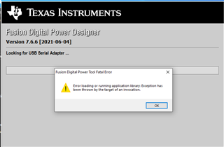
I tried 3 different PC's and get the same erorr and can't continue.

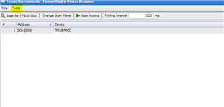
When I install 7.10.1 version it immeatly identifiy the USB-TO-GPIO2 correctly (but doesn't support the TPS38700C)

What is wrong? thanks

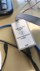
(a pic of the USB blaster)

  • Hello Niv, 

    A TPS38700-Q1 user was recently having problems connecting to the device and we were able to resolve their problem by having them install the following version of fusion digital. let me know if the following works for you.

     TI-Fusion-Digital-Power-Designer-7.9.3 (1).zip

    Regards, 

    Oscar Ambriz 

  • I tried this version now, it connects to TPS38700C and write commands but when I press "Refresh All" all the values are deleted and I get something default.

  • Hello Niv, 

    Glad to hear some progress was made. The "Refresh All" will perform a complete read of the register map and display the current data stored in the device. Typically when using the device i recommend pressing the "Refresh All" button so the interface displays the data stored in the device. Once the refresh has completed the user can make the changes desired and press "Write to Hardware" to complete the change. If the change was completed correctly "Refresh All' can be pressed again and the recently written data will still be present. To better assist could you tell me what change is being attempted? 

    Regards, 

    Oscar Ambriz 

  • Hey Oscar,

    I'm trying to write the Power Up sequence. I try to change the values, click "Write to Hardware", and then "Refresh All". It always goes back to default values.

    I tried to make changes almost everywhere in the registers (manually). They never seem to stay. Tried to observe what is going on with Salea Logic Analyzer, the write commands seem to be OK but every read command gets NAK. This behaviour was also with TI-Fusion-Digital-Power-Designer-7.6.6.

    I don't know what else to do. This EVM is useless in this situation.

  • PEC_CALC_HEX.xlsxHello Niv, 

    Based on the description you provided I believe this behavior is due to the Packet Error Checking (PEC) being enabled by default for the part placed on the EVM. The PEC uses CRC-8 represented by the polynomial C(x)=x^8 + x^2 + x + 1, with CRC initial value set to 0x00. The PEC calculation includes all bytes in the transmission, including address, command and data. The PEC calculation does not include ACK or NACK bits or START,STOP or REPEATED START conditions. 

    Since the PEC byte is not being included in the transmission the device is not recognizing the command. In order to write to the device the user must provide the PEC byte after the Data or disable the PEC requirement. The PEC byte can be calculated using the attached excel sheet. Alternatively one could disable the PEC functionality and write commands will be accepted without the need of a PEC byte. 

    To disable the PEC requirement the user must ensure that bit 0 and 1 of register 0x29 are set to 0. To do this using the software do the following: 

    1. In the initial home page navigate to the "Tools" tab on the top ribbon and select "SAA/SMBUS/I2C Tool". At this point an additional window will pop up. 

    2. Using the tool provide the device address, in this case 0x3C. In the I2C write window type in 0x29h as the register address and 0xC06B as the data. Register 0x29 is the register which controls the PEC, data 0xC0 will disable the PEC, and 0x6B is the PEC byte corresponding to the intended command. The PEC byte can be calculated using the attached excel sheet. 

    Performing the above will disable the PEC functionality meaning that you can now go back to the GUI and the write commands should go through successfully. I should note that this is an oversight in the user's guide and we will work to correct the document. 

    Regards, 

    Oscar Ambriz 

  • Hey Oscar, Thanks for your reply.

    Writing 0xC06B to 0x29 register did not work (NAK), however I was able to write 0x0025 (zeros to all 0x29 register + updated PEC byte) and the GUI did allow me to get rid of PEC flag. Now I am writing and after refreshing, the changes stay and PEC flag don't go red. The problem is when I power down the EVB, all the changes are dropped and I go back to the start (PEC enabled, can't talk with the IC), and I need to write again to disable PEC and make changes stay. I think something is wrong with the internal NVM. PROT1/PROT2 registers 0xF0, 0xF1 are all zeros (no protection).

  • Hello NIV, 

    Unfortunately the TPS38700-q1 does not have programmable NVM. Meaning that when the device is powered off it will default back to its programmed configuration. The references to "NVM" in the datasheet are meant to refer to the preprogrammed configuration in the device that is loaded at power on. I understand the frustration considering the GUI is not optimized to work with PEC. We are currently making an effort to update this device documentation to eliminate common confusion such as this. 

    Regards, 

    Oscar Ambriz 

  • Hey Oscar,

    Thanks for the explanation, the PEC workaround is ok. The lack of programmable NVM is a problem, and TI did not mention it well in the Datasheet.

    I will look for another sequencer with programmable NVM. Thanks for the great help and patience with this issueBlush