This thread has been locked.

If you have a related question, please click the "Ask a related question" button in the top right corner. The newly created question will be automatically linked to this question.

BQ25756E: Inquiry about the BQ25756E device

Part Number: BQ25756E

Tool/software:

Hello,

My customer has some questions about the BQ25756E.

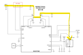
Q1. In the block diagram of BQ25756E below, four N-CH MOSFETs are used. I would like to know the operation of these MOSFETs.
       For example, when charging, is it correct to control HDRV1 and 2 pins to high in S/W as shown in yellow below?
       How should the user control it when charging is complete or when there is no external power source?
       If you have any reference documentation for this, please provide it.
Q2. They plan to use the battery pack below. What can happen if the Cell Voltage Balance is incorrect during charging or discharging?

       - Rechargeable Li-ion Pack : 7-series, 2-parallel array / 25.9V 5.7Ah 147.63Wh

       - Rechargeable Li-ion Pack : 7-series, 3-parallel array / 25.9V 10.35Ah 268Wh

Q3. Are there any example cases where charging may not occur when charging a battery pack using the BQ25756E?

Thanks in advance.

JH

  • Hello JH,

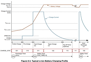
    Q1. The charger automatically controls the 4 FETs and will automatically disable the charger once the battery reaches the charge voltage at the termination current. You can see the charging profile in Figure 8-3 in the datasheet. Let me know if this is what you are looking for:

    Q2. To balance the voltage on the battery packs, the customer will need battery gauge or monitor. Do the battery packs come with a battery gauge/monitor? I can loop in the battery gauge expert to provide a recommendation if needed.

    Q3. Section 8.3.4.1 in the datasheet describes the conditions for the battery charger to start charging:

    Let me know if this answers your questions or if you have any more questions.

    Best Regards,
    Ethan Galloway