This thread has been locked.

If you have a related question, please click the "Ask a related question" button in the top right corner. The newly created question will be automatically linked to this question.

TPS3762: circuit verification

Part Number: TPS3762

Tool/software:

Hi j-garcia, 

Customer: Capgemini

End Equipment – MWLU(Multiple Domain wireless LAN Unit).

Start of Production- 2026.

Project Lifetime Quantity- 7K/Anum.

Sample quantity needed- not required.

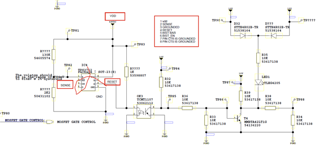
FYR attached the schematics.

please suggest or verify the circuit.

  • Hi Nelavala,

    I have multiple concerns here:

    1. The IC you requested was TPS3762DG3N2DDFRQ1. This device is a fixed threshold device meaning it has internal resistor dividers, In your schematic you also included an external resistor divider. This external resistor divider is not needed and will negatively impact device thresholds and performance.
      1. The maximum current the RESET pin is capable of handing is 5mA. For this reason I would recommend increasing the pullup resistance on the RESET to >12Kohms. This will prevent RESET current from exceeding 5mA for voltages up to 60V(transience). 
    2. The BIST pin is open-drain meaning that it as well will require a pullup to a voltage no greater than 5.5V
    3. You will also need some sort of digital input to BIST_EN / LATCH_CLR. This will allow you to pulse this pin and clear your latched faults, as well as provide the extra added benefit of running built in self tests at your choosing (mainly used in board/device functionality testing).
    4. You state in the red box that CTR and CTS are grounded. These pins are not to be grounded they can either be left floating or have capacitors between them and ground to adjust reset delay and sense delay (glitch immunity) timings. 

    Thanks,
    Joshua