Tool/software:
Hi TI,
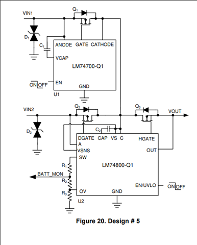
In my custom board, Two inputs are received from two external battery power supplies, 28V each. I need to implement Oring circuit, where these 2 battery power supplies are given to an ORing circuit (LM74720-Q1 U1 and U2) and ORed output VOUT is given to my on-board components.
Now, I'm facing issue where VBAT_1 goes low and VBAT_2 goes high, then EN pin of U1 goes low, thus PD pin of U1 pull down Q2 will be turned OFF, so Vout path will be OFF. Vout will be 0 volts. ORing function is not happening.
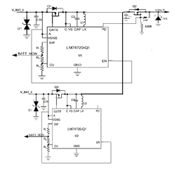

What changes can I do in the attached circuit, to get output voltage as expected as shown in above image?