


Tool/software:
Hi Power Management, I am a FAE intern working on a power supply design project and have been running into some issues with my simulations. Could you assist me in knowing where I could be going wrong with my design or if there could be a simulation issue? I have pasted the schematic below as well as the reasoning for the component selection and configuration.
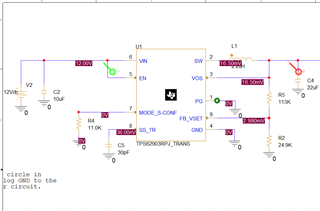
-12V nominal supply as desired nominal input and in range (3V-17V)
-10 micro-farad cap as specified in applications schematic in data sheet
-Mode/S-conf resistor of 11.0K because the desired switching frequency is 1MHz, in auto PFM mode, and uses external feedback for voltage regulation
-SS/TR capacitor of 30pF to get lower soft-start ramp time
-PG hooked to ground (wouldn't let it float in PSPICE simulations)
-SW inductor of 2.2 micro-henry and decoupling capacitor of 22 micro-farad as specified in applications schematic in data sheet for recommended LC filtering for 1MHz switching frequency
-R1 of 113K and R2 of 24.9K to get 3.322V output (~3.3V)
Also, would a 20% tolerance on the inductor and 10% tolerance on the capacitors be appropriate for EVM testing?
