Tool/software:
Hello Everyone,
We are currently working on a design that uses the UCC256601 and as we push towards layout a few questions have been asked about loop stability.
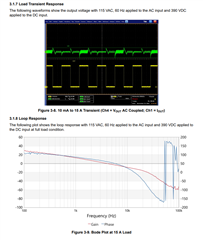
1) Can the Loop Stability tested using Phae Gain analyzer (Bode)
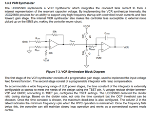
2) Does the VCR Synthesizer maintain loop stability.
I looked around the TI website and even an internet search for “VCR Synthesizer” and totally struck out.
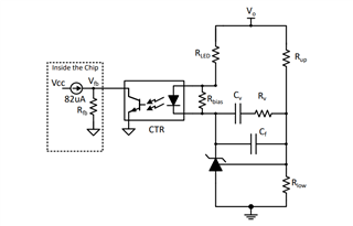
3) Is the loop compensation handled on the input of the opto-coupler in the feedback path.
The UCC256601 datasheet doesn’t cover this at all.
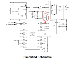
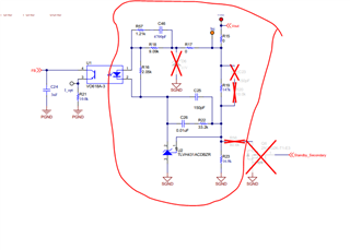
However, the TI Eval Board UCC25660EVM-064 has a complex compensator on the input of the opto.
4) What does “VCR” stand for?