Other Parts Discussed in Thread: TIDA-010000, TIDA-00173, UCC28740
Tool/software:
Thank you very much for your help. Thanks to you, I am fully engaged in the development of SMPS as recommended by TI.
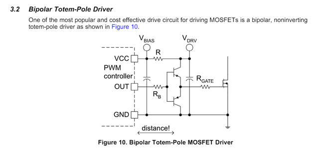
To use SiC MOSFETs (before i asked to here and i recommand upper document), the recommended documents suggest using push-pull circuits.
Reference document :
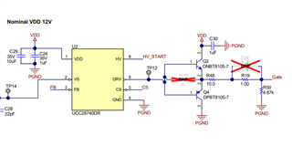
1. TIDA-010000
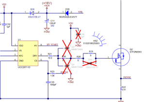
2. TIDA-00173
Questions:
1. Do you select the gate drive circuit based on the MOSFET's Coss value? If so, I am curious if there are specific criteria or calculations for Coss.
2. I would also like to know the criteria for selecting R48, R19, D24, and R50. If there are any reference documents, please let me know.
3. Additionally, some documents show a resistor at the TP12 position, while others do not. I am curious about this as well.
<TIDA-00173>
<TIDA-010000>