LM5123-Q1: Continuous restarts

Part Number: LM5123-Q1
Other Parts Discussed in Thread: BQ24650

Tool/software:

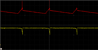
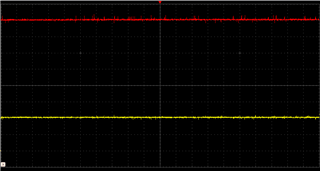
These images are from a LM5123-Q1 boost converter set to 16V target which then feeds a buck converter/battery charger. The left image is what happens if no resistor is placed in series with the AGM battery. The right image has a 2R resistor placed in series with the battery positive terminal. The lower trace (yellow) is the input via a short length of lead. The upper trace (red) is the boost output.

Also, if the input voltage is increased to force the LM5123-Q1 into bypass, the input voltage can then be decreased and the continuous restarts no longer occur. If the input voltage is taken still lower until the LM5123-Q1 stops and then increased to a low voltage for restart, the continuous restarts begin again.

It is important we find an answer to this because the boost converter will be connected to solar cells 24Hrs a day.

  • Hello Laurie,

    Thanks for reaching out to us via e2e.

    What I can tell from looking at the left image is that the power source at the input of the boost stage is not powerful enough to deliver the required peak current.
    Therefore the input voltage breaks down.
    When it falls below the UVLO threshold, the Boost controller goes into reset and everything re-starts again.

    Unfortunately I do not have enough information to properly understand your application.

    Do I understand correctly that you want to
    use solar panel(s) as the source,
    then connect the input of the boost stage directly to the solar panel.
    On the output of the boost stage you want to connect a battery charger which will then charge the AGM battery.
    Is that correct?

    In your experiments (when you took these measurements), what is the power source?
    Do you use the AGM battery as a load (behind the charger) or do you use it as a source?
    Where do you insert hat 2 Ohm resistor? On the input of the boost stage or on the output (even behind the battery charger)?

    Do you not care about a Maximum Power Point Tracking concept?

    Best regards
    Harry

  • Hi Harry,

    Thank you for your fast response,


    The screen shots were from a setup where the boost was fed from a bench power supply starting at 0V and increasing up to around 6V. The other screen shot was using the same supply but I had increased the input voltage until it went into pass through, 16V, and then I had decreased the voltage until I had reached the previous low input voltage. The output of the boost converter feeds a buck converter.


    The question is why, after entering and then leaving pass through mode does it perform as I would have expected yet it will not do it from zero and rising.


    Also, when using an active load on the buck converter, there is no evidence of this restart problem but when a real AGM 18AH battery is used, there is a restart problem until I introduced a 2R resistor in series with the positive battery terminal.


    I have anticipated that there may be no simple answer to my questions so I have looked more closely at MPPT as you suggested and your BQ24650. Is there an easy way to defeat the "Battery present" mechanism because no reverse current would be available in our setup. The output of an MPPT controller would be diode or'ed (diode OR) with mains power when available.

    Thank you

  • Hello Laurie,

    There is a simple answer to your questions:
    A solar battery charger requires more than just a Boost and a Buck in a row.
    On the input side you need a stage that is able to deal with the varying input power (not just voltage but available power)
    and on the output side you will need some current control and battery status monitoring.

    Please be aware that the AGM battery can deliver and also draw a very high current.
    And without any control mechanism, you are creating something like a short on the output of your converter(s).

    The introduction of that 2 Ohm resistor is a very primitive way of limiting the output current.
    But - at 12V - this will limit the output current to 6A which means 72W maximum.

    A rough calculation:
    Including the 2 Ohm resistor: When your input voltage is 6V, the average input current for 72W is 12A; plus an adder for losses which already means around 14A to 15A   AVERAGE current.
    The peak inductor current (input current) can be 50% higher than the average current (or even more, dependent on your chosen inductor and sense resistor) which results in 20A or more.

    For the above calculation, the 2 Ohm resistor was taken into account.
    Without that resistor, the current demand will be much higher.

    I suspect that the current that was drawn by the electronic load was not much more than six Amps.

    So, what you can see from your first screenshot:
    The lab supply is not able to deliver the input current, so the input voltage collapses.
    When the input voltage drops, the converter will see an undervoltage and get reset and try to restart after a while.

    In other words:
    These restarts are happening because your lab supply cannot deliver enough peak current and therefore the input voltage collapses.
    With a different supply this would not happen in the same way.

    But again: 
    when a solar panel is used as a source, it will need to deliver more than 85W average and a peak current of at least 20A when the 2 Ohm resistor is used. 

    Without that resistor, the panel would need to deliver a much higher peak current.

    Below that power and current level (when there is little sun), you will always run into that same trouble that the power source cannot deliver the necessary current.

    Long story short:
    Instead of a simple buck you will need an intelligent battery charger with current limit capability.
    On top, you may also need to monitor the power that gets delivered from the panel and adjust the commanded charging power for the battery accordingly.
    The BQ24650 would also not fit your application, so I had not mentioned it.

    Best regards
    Harry

  • Hi Harry,


    There does not appear to be anything off the shelf that would suit our particular application but I must thank you for mentioning MPPT and putting the idea in my head.


    I have stuck with the LM5123-Q1 and placed a simple current regulator on the output. I have set it up with a resistor/zener on an opamp so that it does not come into effect until the output of the boost reaches the target, sort of an MP setting. From there the setup self regulates and is behaving itself.


    I will get this limited quantity out of the way and look to a new approach for further production.

    Thank you for your assistance.