Other Parts Discussed in Thread: TPS61094, , TPS61023
Tool/software:
Good morning,
I report the last conversation with Antonio Faggio (TI Field Application Engineer), that asked us to open this ticket on TI E2E forum regarding TPS61021 step up application.
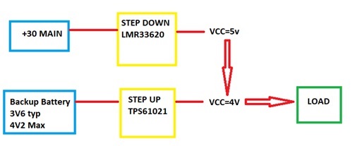
On our application we define the following HW configuration, as shown in the following picture:
INTRO:
- The Step down output voltage is shared with the Step up output voltage (VCC is the net name)
- The EN Step Up is always enabled (ON) and Backup Battery always connected (to be ready to go in tamper condition).
FUNCTIONAL DESCRIPTION:
When +30 Main is present (Power on from external) the output voltage is provided by the Step down and the output is fixed to 5V.
When +30 Main is not connected (Tamper condition), the VCC voltage is provided by the Step down and the output is fixed to 4V.
FOCUS QUESTIONS/ ANALYSIS:
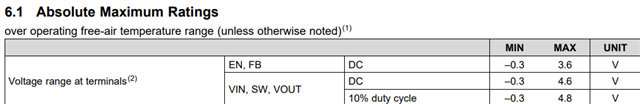
- Vout step up operative max = 4V (Absolute max 4V8).
- Vbck battery 4V2 (full charge)
QUESTIONS/ ANALYSIS:
1. On +30ON condition (VCC provided by step down=5V), could there be problems with the step up functional operation?
On its Vout pin there is a voltage of 5V and on its Vin pin there is a voltage of 3V6 (considering its absolute operative).
2. On tamper condition, with Vbck battery full charge (4V2), we expect (and it's confirmed by test) that on VOUT step up output pin the Backup battery = 4V2, although it's set to 4V.
(Functional condition confirmed in the datasheet when Vin > Vout).
In Tamper condition OK, no problem!
3. On +30ON condition, when the backup battery voltage is > 4V we have an extra current consumption of 2A on +30!
We observed that when the VCC is fixed to 5V by the step down, the Vout step up would like regulate the VCC to 4V (with Vin step up > 4V).
This is the condition that generates the extra current consumption of about 2A on +30.
As final unwanted effect seem that the backup battery is direct fully recharged by the VCC!
As HW mitigation, to avoid the extra current consumption described above, the regulation of VOUT step up could be increased to 4V5 (higher than the Vbck battery full charge of 4V2).
In this way, however, the step up would always work out of specification as it has a typical operative voltage of 4V.
Could you please confirm if this could be damage the component? Or would it still be ok, considering the output absolute voltage of 4V8?
I hope I was clear enough in explaining the problem.
Best Regards
Vincent