Tool/software:
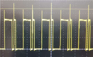
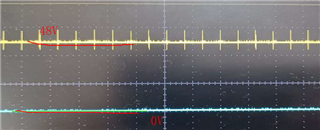
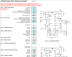
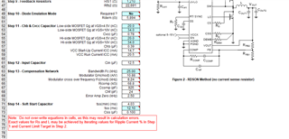
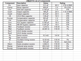
When the LM5116 is designed, the output temperature of the two MOS tubes is high, and the SW has large and small waves.The schematic diagram refers to the official design, and the design output is 24V5A.All usage parameters are referred to the link below:LM5116-5116WG-25116DESIGN-CALC 计算工具 | 德州仪器 TI.com.cn (LM5116-5116WG-25116DESIGN-CALC — LM(2)5116/WG Quick Start Component Calculator)。
See the attachment for details.
I don't know how to upload the attachment and post the picture directly