This thread has been locked.

If you have a related question, please click the "Ask a related question" button in the top right corner. The newly created question will be automatically linked to this question.

LM5155-Q1: Not having symmetric voltage on the out of the SEPIC convetor

Part Number: LM5155-Q1
Other Parts Discussed in Thread: PMP40488, , LM5155

Tool/software:

Dear Engineers,

I'm trying to simulate the following reference design from TI in TINA-TIA:

https://www.ti.com/tool/PMP40488#description

PMP40488 (6-W dual-output SEPIC converter reference design)

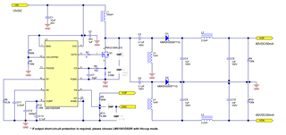
I expected to get a no load voltage of +/-60V, but what I get is +59.95 V and -60.88 V, so it means there is around 1 V difference:

I have also attached the the TI-TINA simulation file for your notice:

SEPIC.TSC

Would you please let me know what is the issue? how can I solve it?

  • Hi Behnam,

    Thanks for using E2E.

    There is nothing wrong. When you calculate the output voltage with the used feedback divider (exact resistor values, no tolerance) you get:

    1/((4.99/(4.99+294)))=59.917V. If you want exacly 60V or a bit more, you can adjust the feedback divider.

    The negative rail is not regulated. That is why the voltage is not that exact. with different loads the negative rail will run away even more.

    Best regards

    Moritz

  • Dear Moritz,

    Thank you for your quick and useful reply.

    In my application I need +/- 60 V (without any difference in between positive and negative voltage rail). Would you please let me know, how can I adjust the current circuit to make the different between +/- output to zero? In fact you mentioned the "The negative rail is not regulated", so how can I regulate this voltage to be exactly the same as the positive rail?

    Regards,

    Behnam,

  • Hi Behnam,

    With this design it is not possible to really have zero difference. You can only regulate on one rail.

    When you have a look at the test report of PMP40488, you can see how the design behaves in reality.  It is also written here, that the negative rail is cross regulated within +-4% over the load range.

    In PMP40488, the inductors L3 and L4 are coupled. If you also couple them in then simulation (perfect, no leakage), you will also get the same voltage for positive and negative rail. However in reality this will not be the case. You will have +- some percent difference over the load range.

    Best regards

    Moritz

  • Hello Moritz,

    Thank you very much for your detailed explanation, how about I use two controllers one for positive rail and one for negative rail?

    Can you please give me an idea how the schematic should look like if I want to use two  LM5155-Q1 one for positive rail and one for negative rail. in this can I can have regulation right? considering there will be an feedback for the negative part as well?

    For positive rail I think I can use the current design (removing the negative rail section ), but how about the negative rail, would you please share a reference design for making a variable negative output voltage (-10V to -60V) from +11V input? 

    Best regards,

    Behnam,

  • Hi Behnam,

    For the negative rail you could use a seperate CUK stage.

    As LM5155 can not accept a negative feedback voltage, you would have to use a level shifter curcuit for the feedback. As a reference plese have a look here:

    https://www.ti.com/tool/PMP30487

    Another oftion for a negative rail is to use a flyback topology with LM5155 or using the inverting buck-boost topology (not possible with LM5155).

    Best regards

    Moritz