A related question is a question created from another question. When the related question is created, it will be automatically linked to the original question.
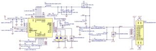
Add a pulldown resistor on NTC pin to avoid tripping thermal overload protection.
Recommended C_CSP is 5x22uF, per datasheet Table 11-2. I would at least include the ability to add 2 more caps in case your loop stability is insufficient.
Recommend C_BUS is 1-4.7 uF per datasheet Table 11-2
We generally see 220 nF from each CC pin to GND for ESD benefit. See datasheet section 8.2, note 4. I suppose your ESD diodes provide similar protection.
One thing I missed in the schematic is the inductor current rating. We recommend 6A saturation current in the datasheet.
Regarding layout, I only have one piece of feedback. Why was a polygon added on the second/green layer for CSN? It doesn't seem to get via'ed anywhere except a matching polygon on the top layer.