This thread has been locked.

If you have a related question, please click the "Ask a related question" button in the top right corner. The newly created question will be automatically linked to this question.

"I've attempted to simulate the design provided by the manufacturer, but it doesn't seem to be working correctly"

Part Number: UCC28C43-Q1
Other Parts Discussed in Thread: UCC28C43, UCC28C53, UCC28C59

Tool/software:

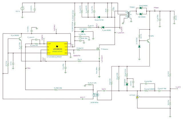
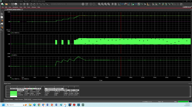
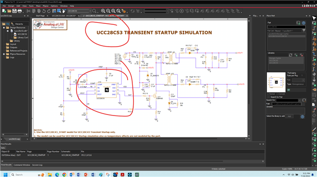
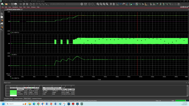
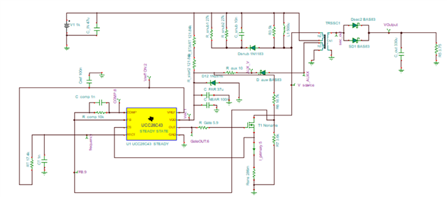
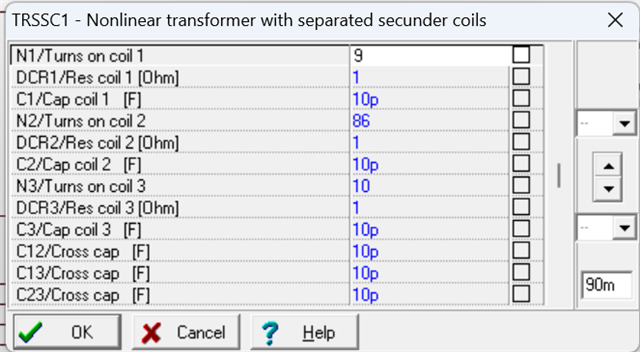
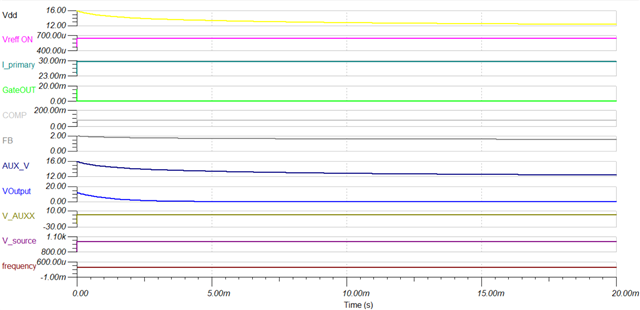
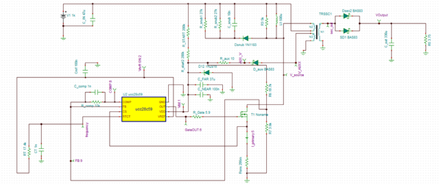
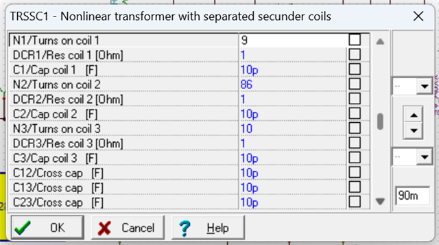
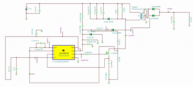
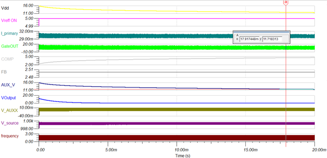
I've been trying to simulate the design provided by the manufacturer, but I'm encountering issues. The output is consistently zero, although the feedback voltage reads 2.5V, which is puzzling since the optocoupler is not ON. I've verified that the transformer's turns ratio matches the specifications given in WEBENCH. Additionally, I have tried referencing both the feedback and the compensation to ground for stability and consistent reference, but the problem still persists. How can the feedback show 2.5V input when the opto-coupler is not active? I'm looking for insights into what might be causing this discrepancy and how to resolve it.

HighVolt_flyback.TSC

  • Try starting with any of the UCC28C43 TINA models. From your end, verify they as they are provided in the product folder. Slowly make the changes you need for your design, change the IC model to suit.

    Regards,

    Steve

  • I've been working on designing my circuit, but I've encountered persistent errors. To troubleshoot, I decided to try out the designs available on Texas Instruments' website. Despite these efforts, I'm facing a puzzling issue: the simulation indicates a feedback voltage of 2.5V, even though the voltage is not being induced in the secondary winding. This is confusing because the output drive of the IC appears to be functioning correctly. Not even the WEBENCH design works when I replicate it exactly. The only component I had to copy from another design was the optocoupler, since I couldn't find it in the existing TINA models. I'm only using the design from the web to evaluate, yet I can't seem to make it work. Is there something I'm missing or not understanding? I've been trying to fix this for a long time and would greatly appreciate any insights or advice

  • I'm not sure about the opto but start with the attached design which is a PSR flyback...swap the UCC28C43 to the UCC28C5x then sim and add more to slum176.tscdebug the sim file.

    Steve

  • I've already tried using UCC28C5X with both PSpice and TINA, but it's not working. That's why I'm trying to get the simulation to work. Not even the WEBENCH design works when I replicate it exactly. If any design from the web works, I can customize it to my requirements. However, the replicated model isn't showing the expected results. There is something I'm missing or not understanding.

  • Are you saying the UCC28C4x design works for you but then you only replace the UCC28C4x with UCC28C5x and the design that previously worked with UCC28C4x now does not work with the p2p compatible UCC28C5x? The UCC28C4x design works on my side in TINA and PSPICE for TI.

    Everything is working on my side and below are some screen captures and step by step to describe what I did. This sim file is not using an optocoupler (PSR) but you can at least see that the simulation models for UCC28C43 AND UCC28C53 are working as they should.

    UCC28C43 Transient Model:

    OUT, +VOUT1, +VOUT2:

    UCC28C53 Model:

    Delete UCC28C43 and replace with UCC28C53:

    UCC28C53 model works in UCC28C43 Sim file:

    Steve

  • Thank you!

    UCC28C4'series i have tina model, don't know why transformer is not inducing on the N1 side(secondary winding in this case).

    Same design won't work with UCC28c5'series Vref is 0, no gate drive voltage and more.

    UCC28C59 results attached below, it is not working at all,

    I have not worked with Transformer. I appreciate help from your side. I Have spent alot of time, still i see no progress.

  • V1 is zero, and what is V2 here, i don't see any other source other then V1 which is zero.

    Transformer parameters:

    turns ratio is 66:1, trying to drop 1000V to 15V. When voltage is not getting induce in secondary winding, how can i see Signal Labled AUX_V as 11V. V_AUXX  is still zero.

    Thank you.

  • I will not be able to sim it for you. I've only shown that the UCC28C5x model is working. In your TINA sim, break it down further to the most basic application to convince yourself. I would temporarily bypass the startup, bootstrap, FB. UVLO is different between the two PWMs you are using...maybe try biasing VCC directly with a DC supply?

    Steve

  • Meaning VDD?  My input range is 400-1000V, can't bypass it. I tried bypassing it the very first day of trying to simulate. 

  • You're debugging the sim...you can bypass startup by removing the start-up resistors, you can even remove the bootstrap winding connection for now and place a DC supply on VDD. You will need to do your own debug of the sim model since you are building it yourself. 

    Steve