This thread has been locked.

If you have a related question, please click the "Ask a related question" button in the top right corner. The newly created question will be automatically linked to this question.

LM51551-Q1: DC-DC convertor variable output- Using potentiometer in the output

Part Number: LM51551-Q1

Tool/software:

Dear Engineers,

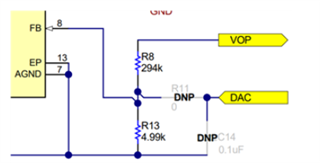
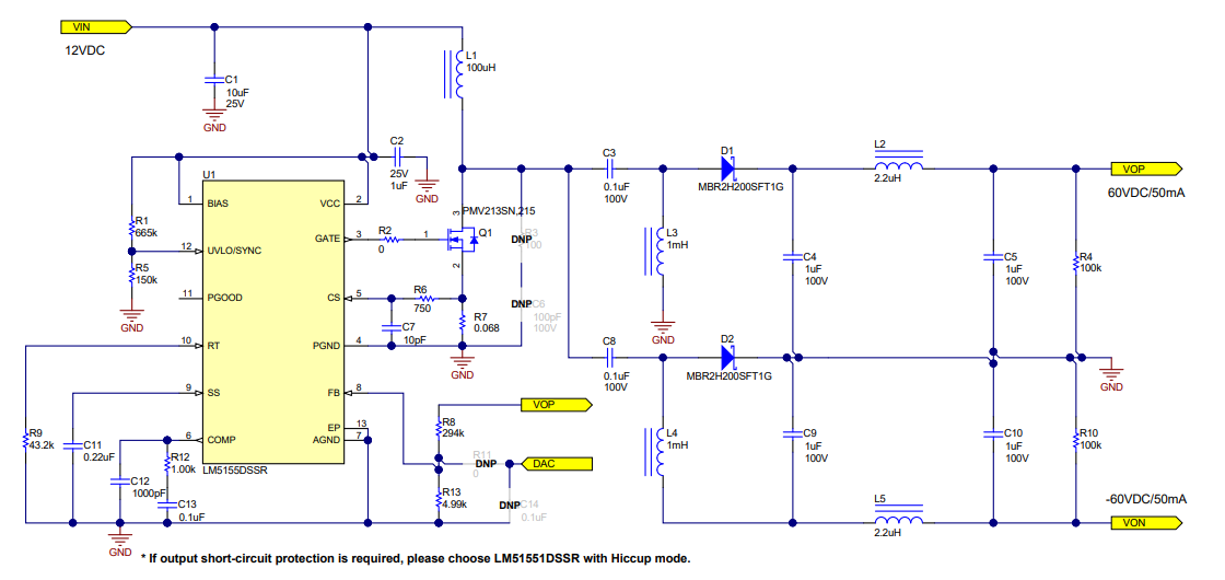
I wan to make the output of the following circuit variable:

I plan to use a digital potentiometer as follows:

Digital Potentiometer 50k Ohm 1 Circuit 64 Taps I2C Interface 10-MSOP

https://www.digikey.ee/en/products/detail/analog-devices-inc/AD5258BRMZ50-R7/995730

Should I replace this with R8 or R13?

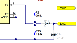
I want the variable output be from +/-5 V to +/-60 V, would you please let me know what should be the range of the Digital Potentiometer?

Regards 

  • Hi Behnam,

    Thanks for reaching out.

    It is better to replace the lower FB resistor. The range would be from 5k to 73.75k for 60V-5V with the used upper FB resistor.

    I recommend to use the DAC input instead, and manipulate the feedback voltage by applying a voltage here if you are using a MCU anyway.

    Best regards

    Moritz

  • Hello Moritz,

    Thank you very much. 

    Would you please let me know what should be voltage range for feedback voltage (FB pin of the IC) that we need to apply for 5V-60V?

    Regards 

  • My next question that, considering I want to use a DAC to apply voltage to FB, I think the range should be between (0.167 V to 1 V)?

    Now, my question is if R13 and R8 are in the circuit, in the feedback node there is already a voltage, then if I apply another voltage to this point what will happen? Maybe I should remove R13 or R8 or both for the sake of using DAC?

    Regards 

  • Hi Behnam,

    The powerstage designer tool, which i linked in your last post, has a tool that calculates exactly this for you.

    The section is called "Dynamic output scaling".

    You can find a detailed description of the theory also here: https://www.ti.com/lit/ug/tiduca8/tiduca8.pdf 

    Both resistors, R8 and R13 stay there, just R11 has to be added.

    Best regards

    Moritz