HD3SS3220: AC Coupling Capacitors on data lines

Part Number: HD3SS3220

Tool/software:

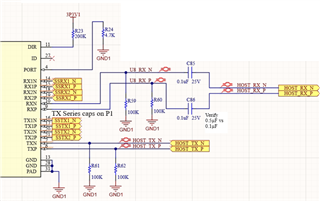
We typically add 0.1µF series capacitors for the USB SS lines but in the UFP EVM schematic, it list 0.5µF capacitors. What is the reasoning behind the 0.5µF value and is there any downside to using 0.1µF capacitors? I understand that the mux lines aren't polarity sensitive but just want to make sure AC coupling capacitor placement is on the transmitter side. Are my connections and its directions valid?

  • Hi,

    The HD3SS3220 EVM is a passive MUX that sits between a USB host and device. The USB spec requires the total capacitance on a USB line to stay within 75nF - 265nF. We use higher-value capacitors near our MUX so that the total capacitance does not drop below 75nF.

    In the application for this EVM specifically, lower value capacitors would combine with capacitors near the USB host and capacitors near the USB device to drop the total capacitance too low. 

    is there any downside to using 0.1µF capacitors?

    Not necessarily. USB3 transmitters are often AC coupled with one set of 0.1uF capacitors. This is ok, because the total capacitance is within the 75 - 265nF spec. 

    It seems like you have the 0.1uF capacitors on the RX pins. If you want to AC couple the RX lines, you need to use capacitors with 330nF as the value.

    This is because a 330nF capacitor on the RX of your host will combine with the 100nF capacitor on the TX of a connected device to bring the total capacitance within the 75 - 265nF spec.

    Best,

    Shane