This thread has been locked.

If you have a related question, please click the "Ask a related question" button in the top right corner. The newly created question will be automatically linked to this question.

BQ25798: QON, VAC1/VAC2

Part Number: BQ25798

Tool/software:

This question is related to the following E2E post.

https://e2e.ti.com/support/power-management-group/power-management/f/power-management-forum/1370113/bq25798-qon-vac1-vac2

① You said that the capacitor on the BAT terminal can be increased to 200μF to prevent VBAT_OVP after removing the battery, but would it be better to mount these capacitors on the BAT terminal side of the BQ25798, or on the battery connector side?

The BQ25798 and the battery connector terminal will be mounted on separate boards and connected with a harness.

② Also, is it acceptable to use the following ECAS for these capacitors?

https://www.murata.com/en-us/products/productdetail?partno=ECASD41C686M040KA0


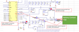
③ If the VBUS pin output is enabled and the 2S battery is disconnected and inserted, is it recommended to mount a 0.047μF capacitor on the CSNUB?
    Let me check if there is any problem with unmounted 2S batteries.

Regards,
Kagawa

  • Hi Kagawa,

    Regarding 1, I recommend placing the capacitors closest to BATP connection, which is the battery pack side of the shipFET.

    Regarding 2, yes because those electrolytic capacitors have very low ESR like a ceramic capacitor.

    Regarding 3, the 0.047uF is not needed for 2S application, especially if you are adding 200uF of low ESR capacitance.

    Regards,

    Jeff

  • Hi Jeff-san,

    Using BQ25798EVM, we found that placing the ECAS capacitors as close as possible to the drain side of the Ship FETs will help to prevent VBAT_OVP when the battery is removed. (ECAS 68μF/16V 2 pcs in parallel)
    Therefore, we have incorporated this countermeasure into the actual circuit diagram, and we would like to confirm that our understanding is correct, so we would appreciate a review.
    If you have any concerns about the configuration around the charger, we would appreciate your feedback.
    In particular, we would like you to confirm the location of the ECAS capacitor you mentioned, the BATP terminal, and the BAT terminal configuration.

    BQ25798_ChargingSpec_20240806.pdf

    BQ25798_Charger_schematic_20240806.pdf

    Regards,
    Kagawa

  • Hi Kagawa,

    The capacitor placement is correct.

    Regards,

    Jeff