This thread has been locked.
If you have a related question, please click the "Ask a related question" button in the top right corner. The newly created question will be automatically linked to this question.
Tool/software:
This is a follow-up for the thread at
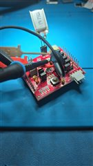
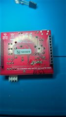
I now have a BQ25120AEVM and have further information about this issue which still needs resolving. I am able to reproduce the issue with the EVM (by soldering capacitors between the output power plane and GND plane) so this should allow support to replicate and analyze the issue better.
Large capacitive loads cause the issue and the amount of capacitive load needed to produce the issue greatly varies between BQ chips installed.
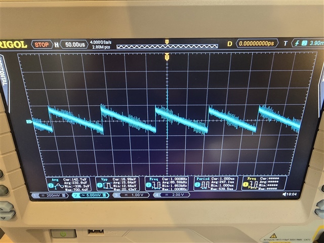
The following images show the waveform of the BQ25120AEVM under different conditions:
1. BQ25120AEVM with 8.2K load resistor:
This is the expected switching behavior since the is no capacitive load.
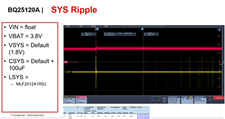
2. BQ25120AEVM with "good" BQ chip with 8.2K load resistor and 3 to 5 22uF caps load:
The caps have little effect on BQ switching behavior and only reduce ripple as expected. "good" BQ units function normally with even 5 or 6 x 22uF caps.
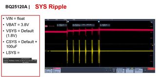
3. BQ25120AEVM with "bad" BQ chip installed and with 8.2K load resistor and 3 to 5 22uF caps load:
Different BQ chips show this switching behavior with different capacitive loads. Some have normal switching behavior with even 6 22uF caps while some show the switching behavior below with only 3x 22uF caps.
We want to avoid this BQ switching behavior since it causes much larger ripple. On our custom PCB design we use 3x 22uF caps in addition to various smaller decoupling caps and about 15% of BQ chips exhibit the noisy switching behavior above.
Hi Philip,
There is always some amount of device-to-device variation that is expected and calibration is taken to minimize the variation. Since output ripple isn't really an item that we spec for this device its possible that a bit more variety can be seen with this specific item.
There may be design steps we can take to minimize this such as changing inductance and layout. To clarify, you are seeing this on the BQ EVM with an additional 66uF or greater of output capacitance and an 8.2kOhm load?
Best Regards,
Juan Ospina
Hi Juan.
Yes we are seeing this with the EVM with 66uF or more capacitive loading and 8.2KOhm load resistor. How much capacitive load triggers the issue is BQ unit dependent. With 132uF this is pretty easy to replicate with the EVM. With less capacitance it is more unit-specific. Note that my sample size is fairly small (about 30 units in pre-production testing total so far).
The behavior with the EVM is very similar to that of our custom PCB so it would seem that layout changes would not help (I assume the EVM has optimal layout)?
Questions:
1. If you can replicate the issue and fix it with inductor changes can you let me know? We experimented with this quite a but but were unsuccessful with 1.8-3.3uH non-saturated inductors so far (on our PCB not the EVM).
2. Is there any way to change BQ calibration values at runtime in order to try to change the switching behavior for units affected by this issue? I would be happy to sign an NDA if this is confidential information. It would save us a lot of trouble because the current plan is to rework all the PCBs with this issue by replacing the BQ for this production run and then design out the BQ in the second hardware revision or implement a reliable fix which meets our ripple requirements.
3. Is there any documentation on what causes this unusual switching behavior? It would be easier to try to resolve it if one could understand the detailed cause.
Cheers
Philip
Hi Philip,
1. If you can replicate the issue and fix it with inductor changes can you let me know? We experimented with this quite a but but were unsuccessful with 1.8-3.3uH non-saturated inductors so far (on our PCB not the EVM).
I will work in lab to try to recreate this behavior and see what improvement can be made from an inductor perspective in order to reduce it. Since I'm working on the EVM I will likely be using higher capacitances. Just to confirm, your PCB has 66uF present at the output?
2. Is there any way to change BQ calibration values at runtime in order to try to change the switching behavior for units affected by this issue? I would be happy to sign an NDA if this is confidential information. It would save us a lot of trouble because the current plan is to rework all the PCBs with this issue by replacing the BQ for this production run and then design out the BQ in the second hardware revision or implement a reliable fix which meets our ripple requirements.
There isn't really a way to do this at runtime unfortunately.
I don't believe there's any documentation on this behavior but I will consult with designers to try to figure out the cause.
For a bit more perspective, can you provide a capture of the SW waveform comparing the switching on both kinds of units?
Best Regards,
Juan Ospina
Thanks Juan.
Our board has 3x 22uF caps plus various smaller decoupling caps which might add up to an additional 10uF. But only about 10-15% of BQ units exhibit the problem with this configuration. If you want to more easily replicate this issue with the EVM without swapping out a bunch of BQ chips then you could use 6x or 7x 22uF caps to reproduce the problem with more BQ chips.
I am currently traveling but can provide the SW waveform in a little over a week...
Cheers
Philip
Hi Philip,
Thanks for the additional context, I'll see what can be done to minimize this behavior.
Best Regards,
Juan Ospina
Hi Philip,
I'm having a tough time recreating your waveform, I'm not see quite as much ripple as you are with an 8.2kOhm load. Can you please share your VIN, VBAT voltage, VSYS setting, I believe I might be missing something from my set up to match your behavior.
Additionally, can you provide a capture of the SW node, I'd like to compare switching behavior as well.
Best Regards,
Juan Ospina
Hi Juan.
Attached please find the same waveform with additional probe on SW (Yellow SW trace is using a passive prove, hence the different scaling). SW appears to be as expected given the output issue.
In general the issue does not happen when also powering VIN (I leave it unconnected). I am only connecting a 70mAH ~3.8V LiPO battery and leaving VSYS at the default 1.8V (I don't have the tool to program the EVM). Note that sometimes you have to wait a bit for the problem and other times the problem goes away after a few minutes (BQ starts the normal expected switching pattern). If you use 6x 22uF capacitive loading along with the 8.2KOhm load resistor I would guess that at least 1/10 BQ units would exhibit the bad switching behavior.
I am also attaching some pics of the EVM and where I soldered the load.
Hi Philipe,
Due to the holiday, Ill provide response on Tuesday.
Best Regards,
Juan Ospina
Hi Philip,
I was able to do some testing and recreate the behavior you were seeing:
I was experimenting with a few inductors. With this inductor I was unable to recreate the behavior:
You can try using this or a similar inductor on your boards to see if that improves the device behavior.
Best Regards,
Juan Ospina
Hi Juan.
I'm glad to hear you were able to reproduce the bad switching behavior and thanks for the 1.5uH recommendation.
Unfortunately that MLF inductor is an 0805 part which does not fit on our boards due to space restrictions (height as well as area). Also, this stops the bad switching behavior for that particular configuration and not understanding the cause of the behavior makes me wonder whether the bad switching behavior won't return with variations in parts tolerances, current, etc. Previously I think I did try a 1.5uH LQM21PN1R5MC0D which did not generally solve the issue.
Questions:
1. Did you determine the underlying cause of the bad switching behavior?
2. Do you think a similar fix can be achieved by adding something like a small 15nH inductor in series with the existing inductor in order to filter out some of the high frequency content which might be causing the bad switching behavior?
Hi Philip,
After discussing with the designers it looks like this can be caused by noise interference or by an offset in the devices comparator which can vary some amount between devices.
Ultimately, they did recommend a smaller inductor on their solution. What inductor size are you using for your solution?
Best Regards,
Juan Ospina
Hi Juan.
I tested some 1.5uH parts and am getting mixed results. Out of 4 different part numbers with similar specs, 2 part numbers fix the issue on 2 problem PCBs that I tested and the other 2 part numbers make the problem worse on PCBs that did not have the issue. Of course 20% variation in inductor value as is typical could make this type of work-around hit or miss...
For this small production run (2K units) we will rework the problem PCBs by changing the inductor. In about 7 weeks I should have more information as to how well this fix works on a larger set of problem BQ parts.
I am still wondering if adding a small series inductor will be a better way of permanently working around this issue. Do you have any thoughts from engineering on this?
Cheers
Philip
Hi Philip,
I am still wondering if adding a small series inductor will be a better way of permanently working around this issue. Do you have any thoughts from engineering on this?
I will look into this with design to see if that might improve the behavior. To confirm my understanding of your suggestion, you'd recommend adding a second inductor in series with the first (between SW and SYS), or is this an inductor in series with the output of the buck converter (i.e. on the other side of the SYS line which provides buck feedback).
Best Regards,
Juan Ospina